
Method for reducing channel switching delay in digital broadcast receiver and digital broadcast receiver using the same

a digital broadcast receiver and channel switching technology, applied in the field of digital broadcast receivers, can solve the problems of inconvenient user's channel switching delay, inability to achieve analog broadcasting, and a considerable amount of time for a screen to become stable after switching broadcast channels, so as to reduce channel switching delay and reduce channel switching delay

Inactive Publication Date: 2006-03-02
SAMSUNG ELECTRONICS CO LTD
View PDF31 Cites 13 Cited by
  • Summary
  • Abstract
  • Description
  • Claims
  • Application Information

AI Technical Summary

Benefits of technology

[0015] The present invention provides a method and an apparatus for quickly switching channels in a digital broadcast receiver.
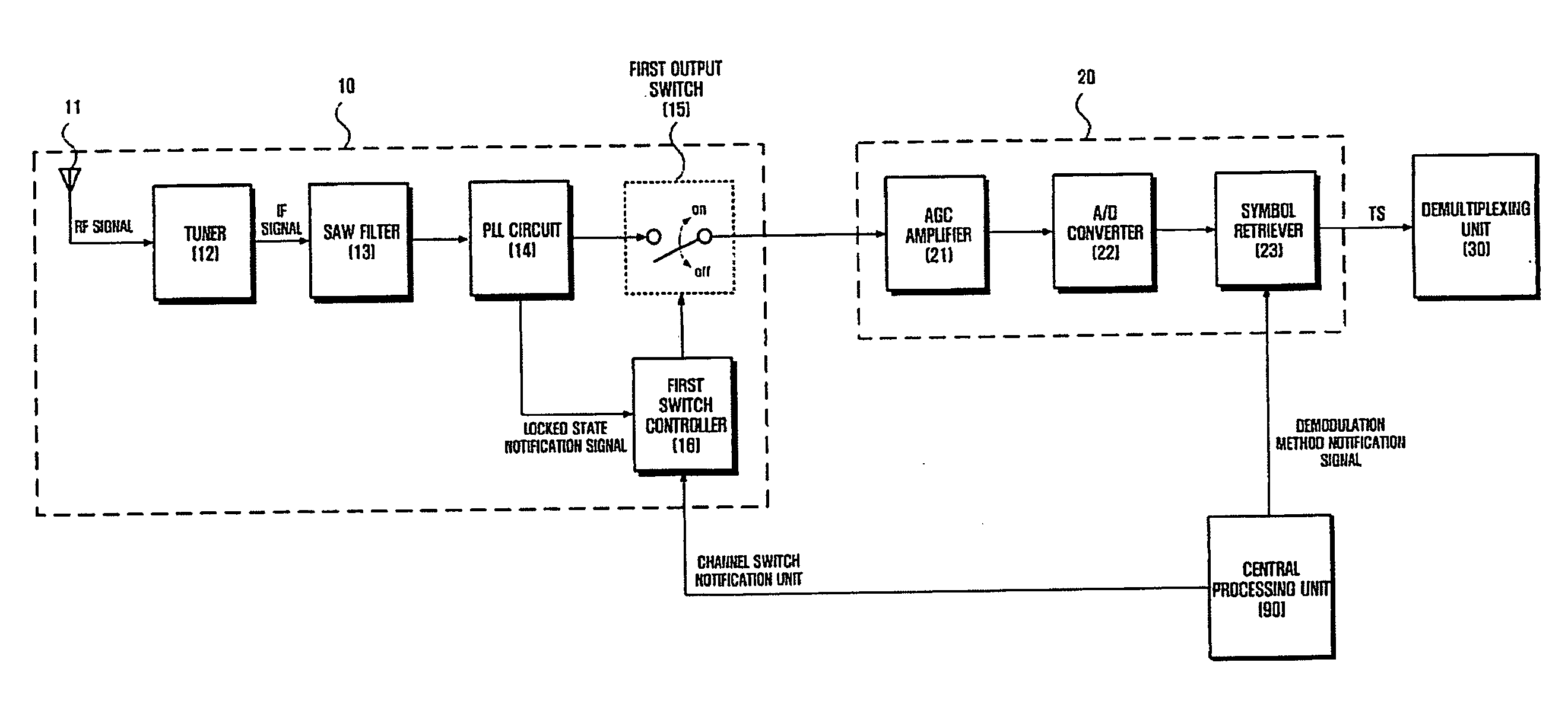
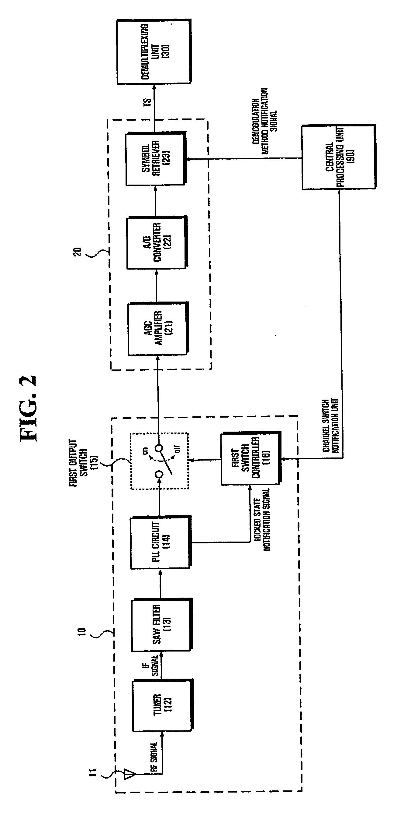
[0016] The present invention also provides a method and an apparatus for starting a demodulation without delay after stabilizing a phase locked loop (PLL) circuit in a tuner.
[0021] The signal reception unit may include a tuner, which converts the received broadcast signal into an IF signal, a surface acoustic wave (SAW) filter, which removes signals of channels adjacent to the channel of the IF signal and noise signals, a phase locked loop (PLL) circuit, which controls a signal output from the SAW filter to enter a locked state and transmits a locked state notification signal to a first switch controller when the output signal of the SAW filter enters the locked state, the first switch controller, which controls a first output switch so that an output signal of the signal reception unit is prevented from being input to the digital demodulation unit when the digital broadcast receiver is switched to the new channel, and controls the first output switch so that the output signal of the signal reception unit is input to the digital demodulation unit when the locked state notification signal is received from the PLL circuit, and the first output switch, which is turned on and off by the first switch controller.
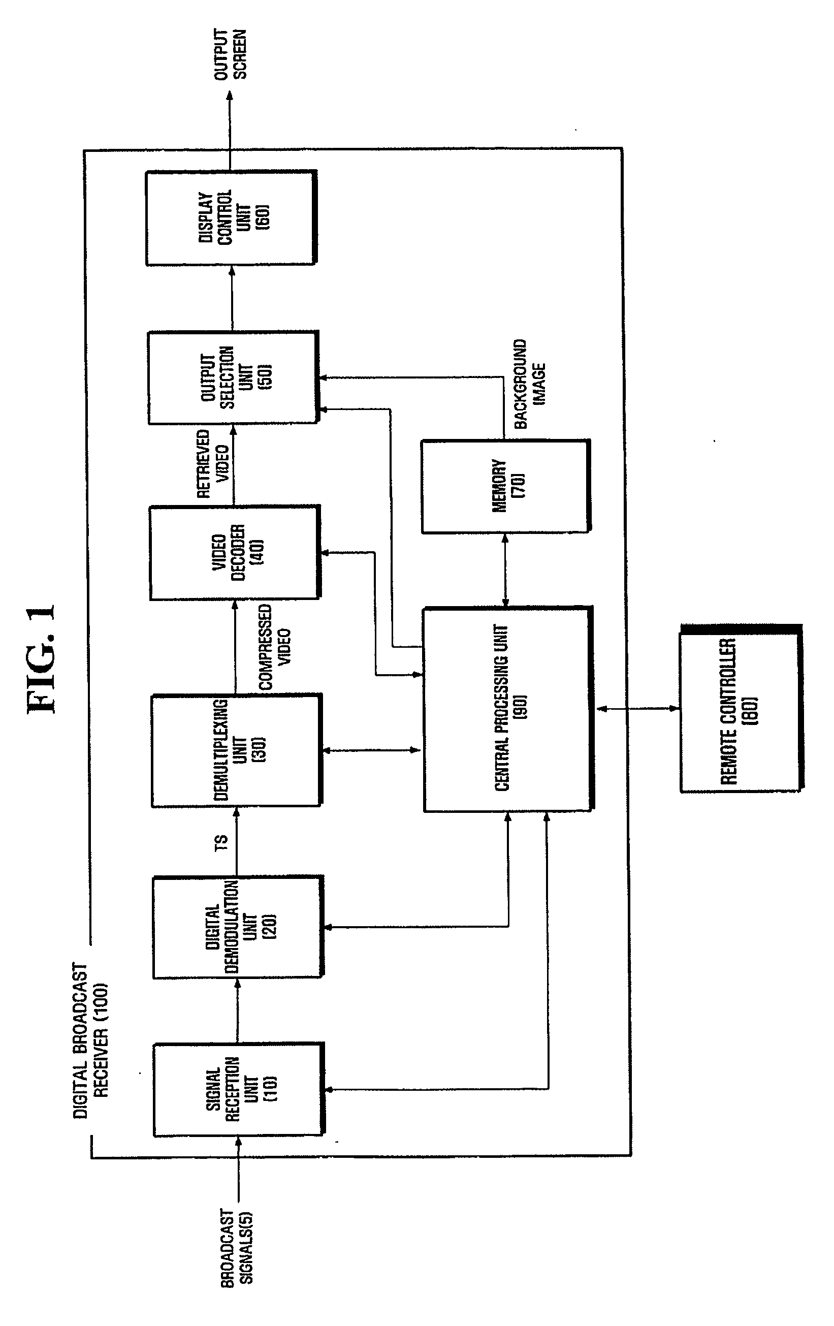
[0024] According to another aspect of the present invention, there is provided a method of reducing channel switching delay in a digital broadcast receiver including receiving a channel switch command, receiving a broadcast signal of a channel to which the digital broadcast receiver is switched in response to the channel switch command and retrieving a transport stream, retrieving a video image from a video signal of the transport stream, and sensing a first intra frame of the video signal input to the digital broadcast receiver after the digital broadcast receiver is switched to the new channel and controlling the video image to be output.
[0025] The method of reducing channel switching delay may further include controlling a background image stored in a memory to be output until sensing the first intra frame of the video signal input to the digital broadcast receiver after the digital broadcast receiver is switched to the new channel.

Problems solved by technology

Due to recent developments in digital broadcast technology, photos and voice taken / recorded in a studio can be transmitted almost losslessly to a user's home together with a variety of additional information, which is not possible in analog broadcasting.
In digital broadcasting, a highly efficient data compression method, such as a Moving Picture Experts Group (MPEG) compression method, is used, and thus, unlike in analog broadcasting, it takes a considerable amount of time for a screen to become stable after switching broadcast channels.
This channel switching delay is inconvenient to users.
However, in digital broadcasting, it takes about ten times more time than in analog broadcasting to normally provide a broadcast program to a user after switching channels, which the user may perceive to be very inconvenient.
In general, no specific detection methods are used to detect the amount of time required to stabilize a signal obtained as a result of performing the above operations in the conventional digital broadcast receiver.
Conventionally, an MPEG decoder is generally set to have a delay time of more than 1.5 sec to wait for an I frame, which results in an increased amount of time required to switch channels.
In this case, however, an abnormal screen may be temporarily provided to a user after switching channels, which is highly inconvenient and undesirable.

Method used


Image

  • Method for reducing channel switching delay in digital broadcast receiver and digital broadcast receiver using the same
  • Method for reducing channel switching delay in digital broadcast receiver and digital broadcast receiver using the same
  • Method for reducing channel switching delay in digital broadcast receiver and digital broadcast receiver using the same

Examples


Embodiment Construction

[0034] Reference will now be made in detail to the embodiments of the present invention, examples of which are illustrated in the accompanying drawings, wherein like reference numerals refer to the like elements throughout. The embodiments are described below to explain the present invention by referring to the figures.

[0035] The present invention will now be described more fully with reference to the accompanying drawings, in which preferred embodiments of this invention are shown. Advantages and features of the present invention and methods of accomplishing the same may be understood more readily by reference to the following detailed description of preferred embodiments and the accompanying drawings. The present invention may, however, be embodied in many different forms and should not be construed as being limited to the embodiments set forth herein. Rather, these embodiments are provided so that this disclosure will be thorough and complete and will fully convey the concept of...


PUM


Abstract

A method and an apparatus for reducing channel switching delay in a digital broadcast receiver are provided. The digital broadcast receiver includes a signal reception unit, which receives a broadcast signal and converts the received broadcast signal into an intermediate frequency (IF) signal, a digital demodulation unit, which retrieves a transport stream from the IF signal, a demultiplexing unit, which extracts a video signal from the transport stream by parsing the transport stream, a video decoder, which retrieves a video image from the video signal by decoding the video signal, and an output selection unit, which prevents a background image from being output and outputs the video image when sensing a first intra frame of the video signal input to the video decoder after the digital broadcast receiver is switched to a new channel.

Description

CROSS-REFERENCE TO RELATED APPLICATION [0001] This application claims benefit from Korean Patent Application No. 10-2004-0067914 filed on Aug. 27, 2004 in the Korean Intellectual Property Office, the disclosure of which is incorporated herein by reference in its entirety. BACKGROUND OF THE INVENTION [0002] 1. Field of the Invention [0003] The present invention relates to a digital broadcast receiver and, more particularly, to a method and an apparatus for reducing channel switching delay in a digital broadcast receiver. [0004] 2. Description of the Related Art [0005] A digital broadcast receiver is an apparatus that restores original digital data from a broadcast signal transmitted according to a digital transmission scheme. A digital broadcast transmitter, i.e., a broadcast station area (hereinafter, referred to as a head end) converts an analog signal into a digital signal comprised of 0 and 1 using digital technology, compresses the converted signal together with other informatio...

Claims


Application Information

Patent Timeline
Patent Type & Authority Applications(United States)
IPC IPC(8): H04N7/12H04N5/50H04N5/44
CPCH04N5/4401H04N21/4384H04N5/50H04N21/426H04N21/43
Inventor KIM, CHUL-MIN
Owner SAMSUNG ELECTRONICS CO LTD
Learn More