Optical receptacle with low transmission and photoelectric conversion module for the same

a technology of optical receptacles and conversion modules, applied in the field of optical receptacles with low transmission and photoelectric conversion modules for the same, can solve the problems of increasing the total component count of the optical receptacle, increasing the transmission loss of optical signals, etc., and achieves excellent noise resistance, reduce transmission loss, and minimize the effect of distance variation

Inactive Publication Date: 2006-03-02
MATSUSHITA ELECTRIC WORKS LTD +1
View PDF7 Cites 7 Cited by
  • Summary
  • Abstract
  • Description
  • Claims
  • Application Information

AI Technical Summary

Benefits of technology

[0019] According to this optical receptacle of the present invention, it is possible to provide the following advantage in addition to the above-described advantage of reducing the transmission loss. That is, when the optical plug is connected to the optical receptacle, the optical transmission medium supported by the optical plug can be inserted into the tubular projection such that the top end of the optical transmission medium abuts against the partition wall. In other words, the partition wall functions as a stopper for the optical transmission medium. Therefore, it is possible to minimize variations in distance (gap) between the optical device and the optical transmitting medium, and stably provide a constant optical coupling efficiency therebetween.
[0020] As a further preferred embodiment of the present invention, the optical receptacle comprises a receptacle housing for accommodating the module housing therein, which is used for connection with the optical plug, and has a front opening, through which the optical plug can be inserted into a plug accommodation space defined in the receptacle housing, a rear opening, through which the photoelectric conversion module is accommodated in the receptacle housing such that the tubular projection of the module housing projects in the plug accommodation space, and the rear opening is closed by an electromagnetic interference shielding member. In particular, when the photoelectric conversion module is prevented from the electromagnetic interference by the shielding member in cooperation with the above-described shield layer formed on the exterior surface of module housing, it is possible to provide excellent resistance to noise.
[0021] A further concern of the present invention

Problems solved by technology

However, in the conventional optical receptacles described above, since the optical couplers 200 such as the optical-fiber members having the required length or the sleeves 85 are disposed between the top ends of the optical fibers supported by

Method used


Image

  • Optical receptacle with low transmission and photoelectric conversion module for the same
  • Optical receptacle with low transmission and photoelectric conversion module for the same
  • Optical receptacle with low transmission and photoelectric conversion module for the same

Examples


Embodiment Construction

[0044] An optical receptacle according to a preferred embodiment of the present invention is explained in detail below.

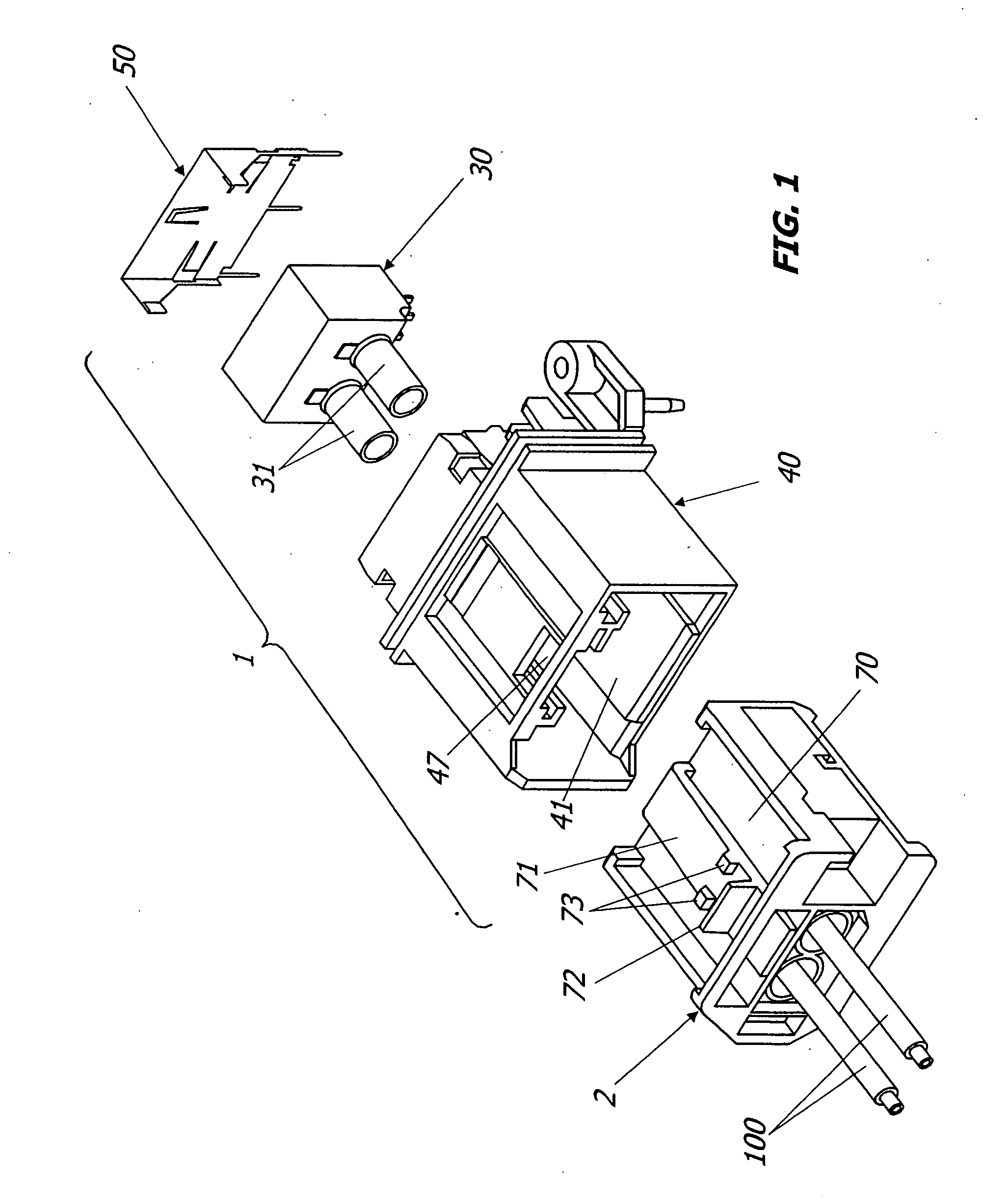
[0045] As shown in FIG. 1, the optical receptacle 1 of this embodiment is connectable with an optical plug 2 supporting one ends of a pair of plastic optical fibers (POF) 110 as an optical transmission medium, and preferably used for data communication between a data base connected through the other ends of the optical fibers 110 and an on-board electric equipment such as CD, DVD, GPS and car telephone.

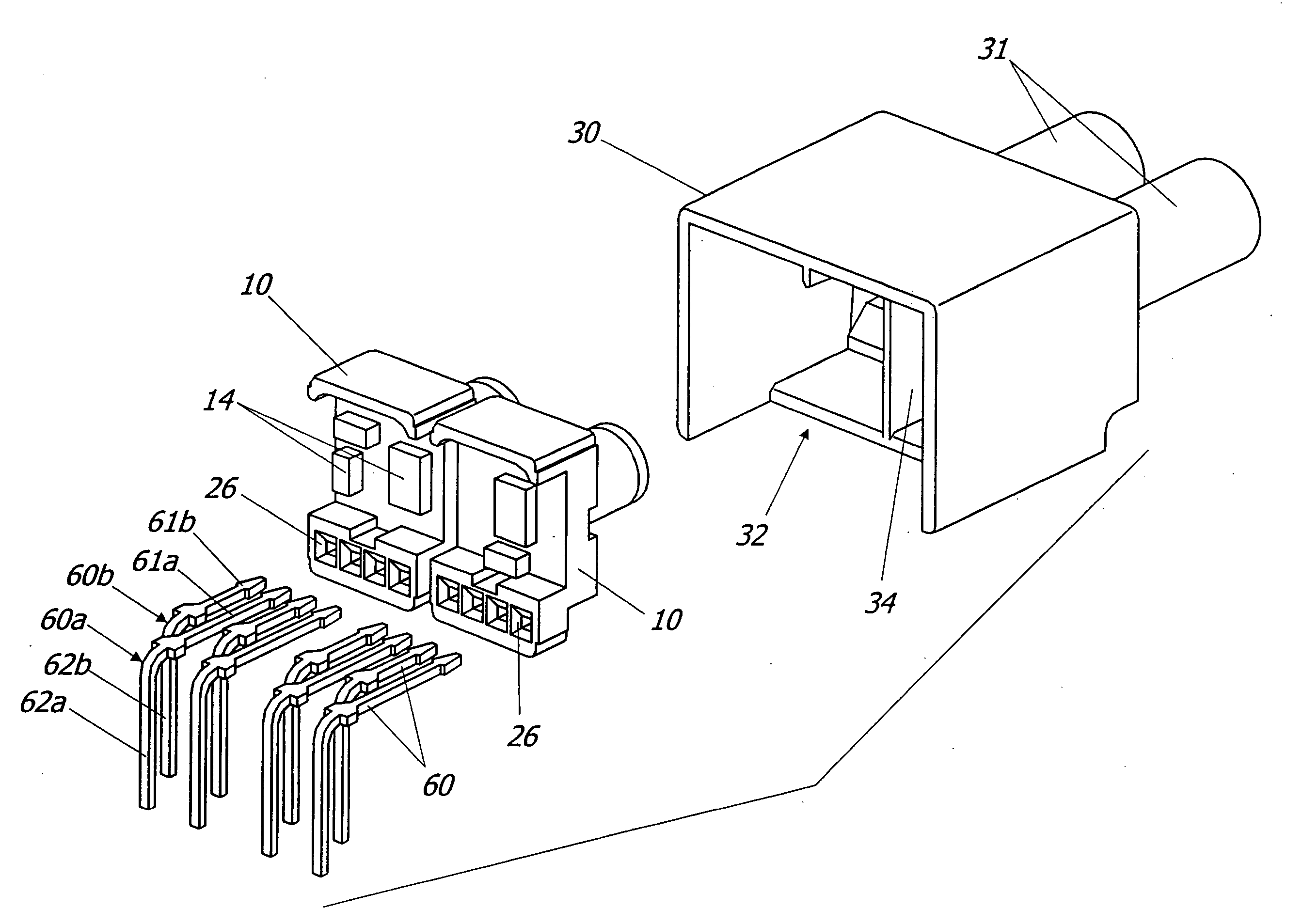
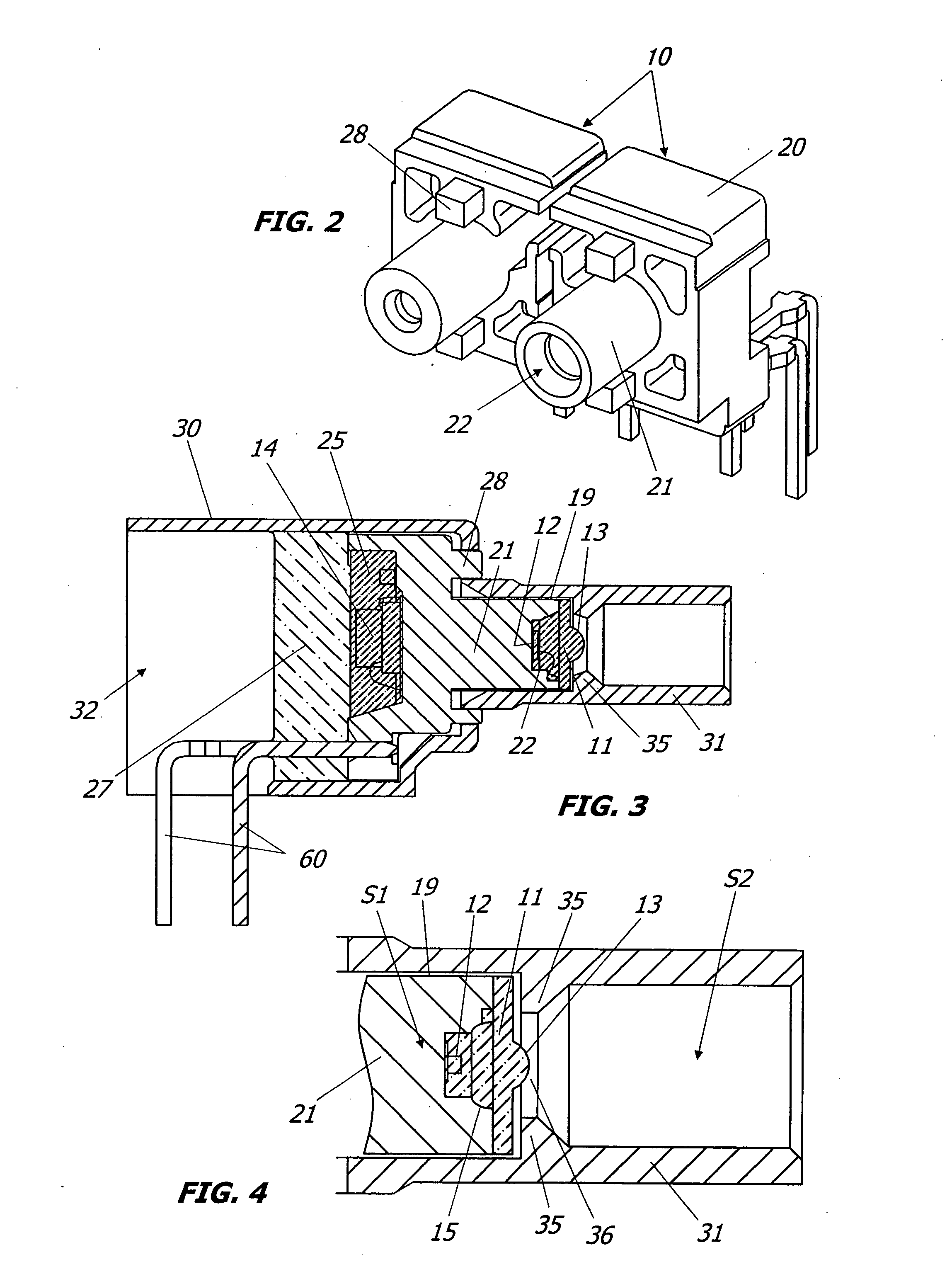
[0046] As shown in FIGS. 1 and 2, the optical receptacle 1 is mainly composed of a pair of photoelectric conversion modules 10 each having the capability of making photoelectric conversion between light signals transmitted through the optical fibers 100 and electrical signals used in the electrical equipment, a module housing 30 of a resin molded article for accommodating the photoelectric conversion modules 10 therein, a receptacle housing 40 for accommodating the ...


PUM


Abstract

An optical receptacle with low transmission loss, which is connectable with an optical plug, is provided. The optical receptacle includes a photoelectric conversion module having the capability of making photoelectric conversion between light signals and electrical signals, and a module housing. The photoelectric conversion module is a molded interconnect device (MID), which is provided with a module body having a post, an optical device mounted on the post, and an electrical circuit mounted on the module body. The module housing has a tubular projection, into which an end of the optical fiber supported by the optical plug can be inserted. When the optical plug is connected with an optical receptacle, the end of the optical fiber is positioned in the tubular projection so as to be in a closely opposing relation to the optical device mounted on the post.

Description

TECHNICAL FIELD [0001] The present invention relates to an optical receptacle connectable with an optical plug having a light transmitting medium such as an optical fiber, and a photoelectric conversion module for the optical receptacle, which has the capability of making photoelectric conversion between light signals transmitted through the optical transmission medium and electrical signals. BACKGROUND ART [0002] Worldwide developments of high-speed communication system preferably used for transport means such as automobiles, airplanes, trains and shipping are now underway. For example, “MOST®” (Media Oriented System Transport) has been proposed as an optical communication standard in Europe. [0003]FIG. 18 shows a conventional optical connector designed under the “MOST®” standard (“TYCO Electronics & MOST” in Presentations by MOST members on “All Members Meeting Apr. 3, 2001”). This connector is composed of an optical receptacle 1P built in an electronic equipment such as CD, DVD, ...

Claims


Application Information

Patent Timeline
IPC IPC(8): G02B6/36G02B6/38G02B6/42
CPCG02B6/389G02B6/4292G02B6/4246G02B6/4204
Inventor KAMBE, YOSHIAKISHIMAYA, KENICHISHIMOMURA, TSUTOMUHAACK, ALBRECHTHALBACH, PAUL GERHARDGAERTNER, MARKUS
Owner MATSUSHITA ELECTRIC WORKS LTD
Why Eureka
Try Eureka