
Optical access network of wavelength division method and passive optical network using the same

a technology of wavelength division and optical access network, applied in wavelength division multiplex system, electromagnetic transmission, multi-component communication, etc., can solve the problems of network requires large initial investment cost, and may incur serious loss while limiting bandwidth, so as to minimize the initial investment cost of wdm optical access network

Inactive Publication Date: 2006-03-02
SAMSUNG ELECTRONICS CO LTD
View PDF12 Cites 78 Cited by
  • Summary
  • Abstract
  • Description
  • Claims
  • Application Information

AI Technical Summary

Benefits of technology

The present invention is about a network that can offer high-speed internet to both wire and wireless users using a single network. This is done by combining optical signals from a central office and then separating them at a remote node. The network also includes radio relay stations that convert the optical signals into radio signals for wireless transmission. The invention minimizes the cost of constructing the network and allows for the efficient delivery of broadband services to multiple users.

Problems solved by technology

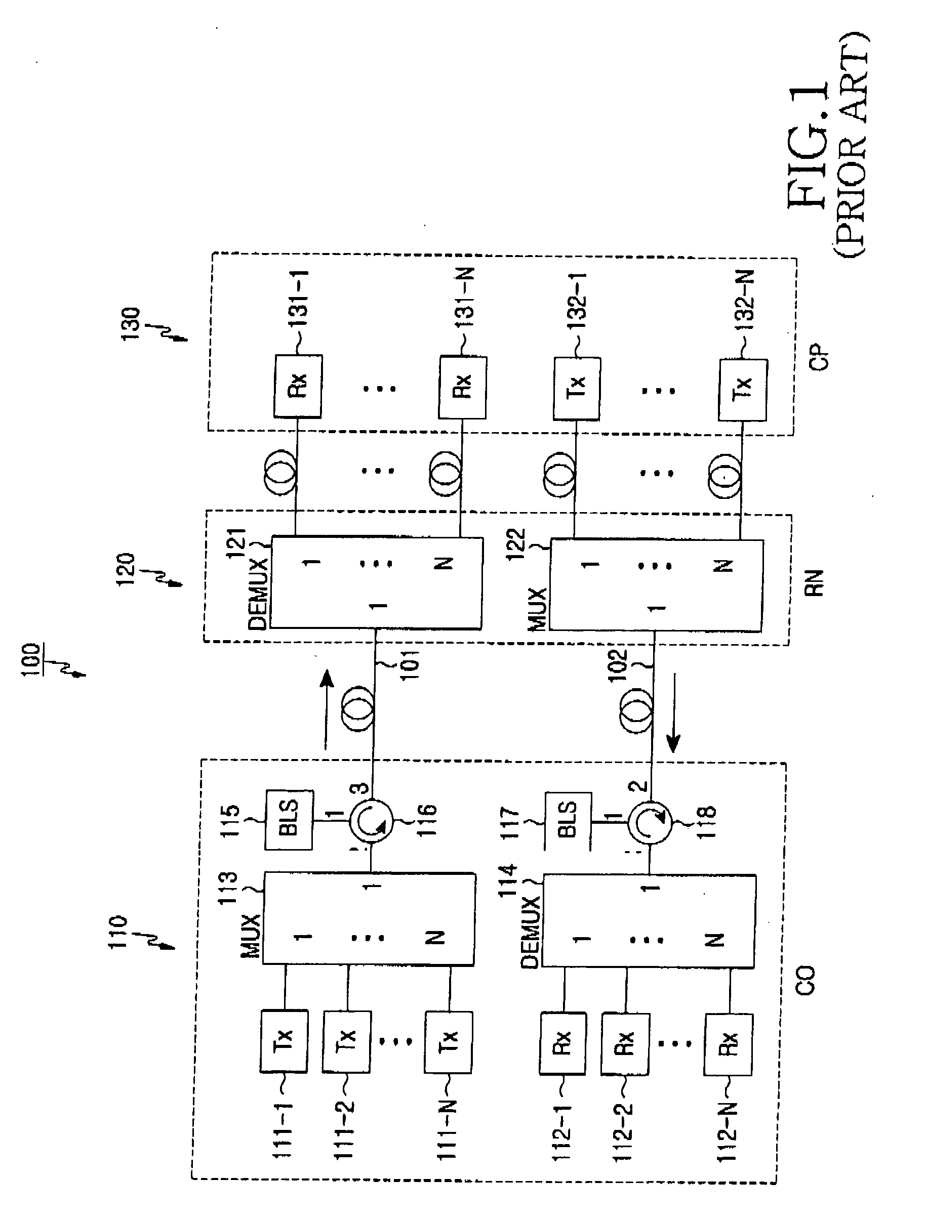
However, for the above-described conventional optical access network, a great amount of initial investment costs is required.
In a wireless network, since mobility and point to multi-point connection are provided, serious loss may occur while limiting bandwidths.
However, since the conventional WDM optical access network provides services mainly for wire network subscribers, not only the network requires great amount of costs for initial investment for and maintenance of the network including optical fiber laying costs, but also extension / growth of the network market is restricted.
In addition, since the radio-over-fiber network also requires a great amount of costs for, e.g., optical fiber laying costs, the spread and usage of the radio-over fiber network is restricted
However, the radio-over-fiber network requires a great amount of costs for initial investment including optical fiber laying costs, and a lot of time is required in order to construct a dedicated radio-over-fiber network.

Method used


Image

  • Optical access network of wavelength division method and passive optical network using the same
  • Optical access network of wavelength division method and passive optical network using the same
  • Optical access network of wavelength division method and passive optical network using the same

Examples


first embodiment

[0035]FIG. 3 illustrates an optical access network 200 according to the present invention. The wavelength division multiplexed (WDM) optical access network 200 includes a central office (CO) 210 for multiplexing first optical signals 203 for wire communication and second optical signals 204 for wireless communication, a remote node (RN) 220 for demultiplexing a multiplexed optical signal 202 received from the CO 210, and a customer premise (CP) 230 for receiving the first optical signals 203 and the second optical signals 204 demultiplexed in the RN 220. The CP 230 includes a plurality of subscribers 231-1 to 213-N, each of which is connected to the RN 220, and a plurality of radio relay stations, each of which is connected to the RN 220.

[0036] The CO 210 includes a broadband light source 214 for generating light with broadband wavelengths, a multiplexer 213, a plurality of light sources 211-1 to 211-N for generating first optical signals 203 wavelength-locked by corresponding incoh...

second embodiment

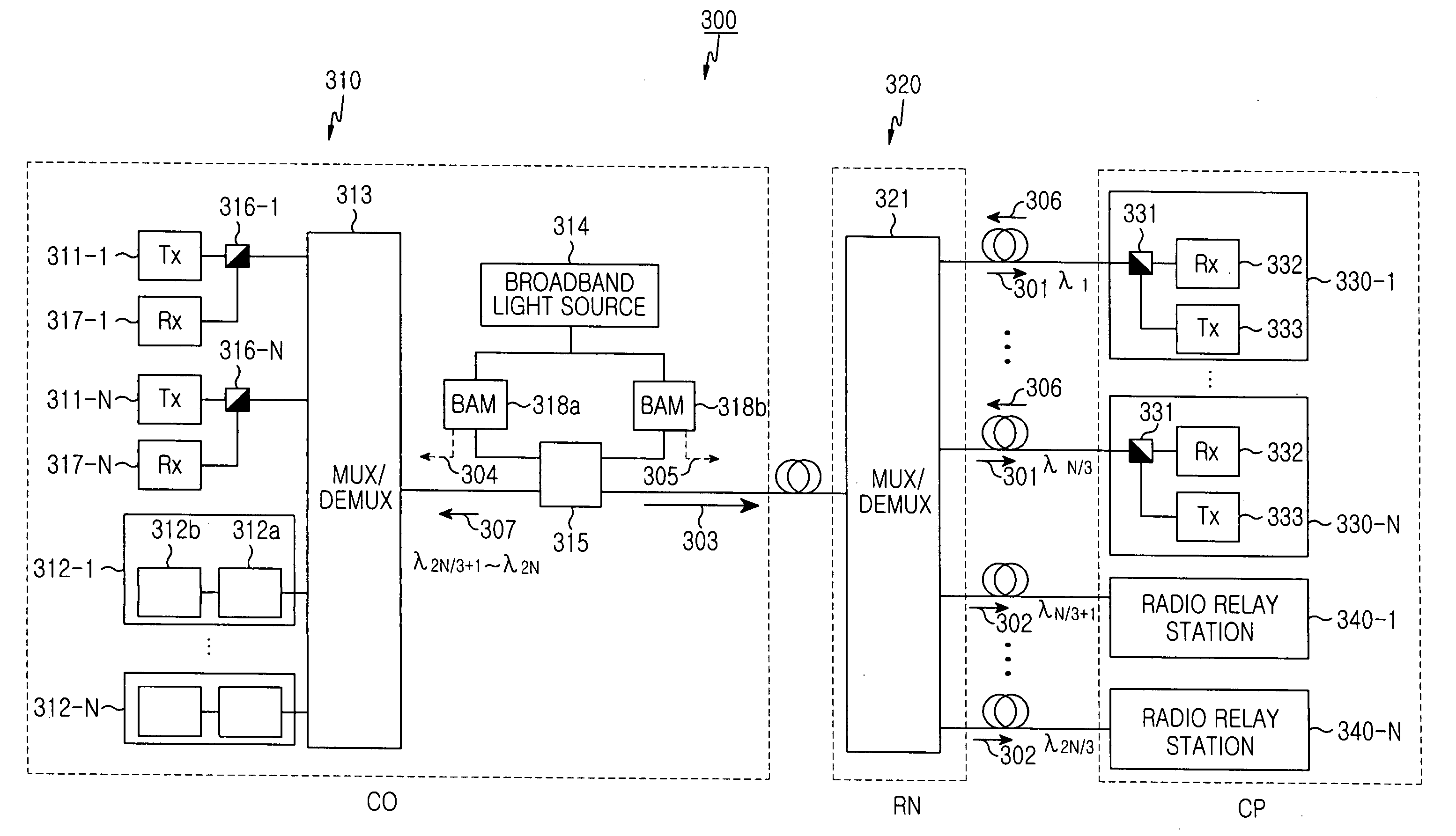
[0046]FIG. 6 illustrates an optical access network 300 according to the present invention. The passive optical access network 300 for bi-directional communication includes a central office (CO) 310 for multiplexing first optical signals 301 for wire communication and second optical signals 302 for wireless communication, a remote node (RN) 320 connected to the CO 310 through an optical fiber and for demultiplexing a multiplexed downstream optical signal 303 received from the CO 310, a plurality of subscribers 330-1 to 330-N connected to the RN 320, and a plurality of radio relay stations 340-1 to 340-N connected to the RN 320. Each of the subscribers 330-1 to 330-N receives the first optical signal 301 with a corresponding wavelength from among the demultiplexed first optical signals and outputs a wavelength-locked upstream optical signal 306 to the CO 310 through the RN 320. Each of the radio relay stations 340-1 to 340-N converts the second optical signal 302 with a corresponding ...


PUM


Abstract

An optical access network of wavelength division method and passive optical network using the same are disclosed. The wavelength division multiplexed optical access network includes a central office for multiplexing first optical signals for wire communication and second optical signals for wireless communication and a remote node connected to the central office through an optical fiber and for demultiplexing a multiplexed optical signal received from the central office. A plurality of subscribers may be connected to the remote node. Each subscriber receives a first optical signal having a corresponding wavelength from among the demultiplexed first optical signals. The network also includes a plurality of radio relay stations connected to the remote node, each radio relay station converting a second optical signal having a corresponding wavelength from among the demultiplexed second optical signals into a radio electric signal and wirelessly transmitting the radio electric signal.

Description

CLAIM OF PRIORITY [0001] This application claims priority to an application entitled “Optical Access Network of Wavelength Division Method And Passive Optical Network Using The same,” filed in the Korean Intellectual Property Office on Aug. 28, 2004 and assigned Serial No. 2004-68215, the contents of which are incorporated herein by reference. BACKGROUND OF THE INVENTION [0002] 1. Field of the Invention [0003] The present invention relates to an optical access network, and more particularly to a wavelength division multiplexed optical access network capable of employing either / both a wire network and a wireless network. [0004] 2. Description of the Related Art [0005] Access network, such as a wire communication system or a mobile communication system, must process data having wider band widths in order to provide various high-capacity multimedia data such as images, moving pictures, as well as voice signals. A wavelength division multiplexed (WDM) passive optical access network has ...

Claims


Application Information

Patent Timeline
Patent Type & Authority Applications(United States)
IPC IPC(8): H04J14/00H04B10/2581
CPCH04B10/25752H04B10/25753H04J14/02H04J14/0226H04J14/025H04J14/0282H04J14/0298H04J14/0246H04J14/0227H04J14/0307H04B10/2581H04B10/25H04B10/00
Inventor LEE, GYU-WOONGLEE, JAE-HOONKIM, YONG-GYOOOH, YUN-JEHWANG, SEONG-TAEKJUNG, DAE-KWANG
Owner SAMSUNG ELECTRONICS CO LTD
Learn More