Ion pump for cryogenic magnet apparatus

Inactive Publication Date: 2006-03-02
VARIAN INC
View PDF3 Cites 14 Cited by
  • Summary
  • Abstract
  • Description
  • Claims
  • Application Information

AI Technical Summary

Benefits of technology

[0009] The present invention, in a first embodiment, achieves vacuum ion pumping in and close to a magnet cryostat with a vacuum ion pump that utilizes the fringe field of the cryostat-housed magnet. Such vacuum ion pump represents a less expensive and less weighty pump than prior art vacuum ion pumps. In one embodiment the elements of the pump form internal structure within the space to be evacuated, such as within the evacuated volume of the magnet cryostat, disposed in a region thereof where a significant component of the fringe field is oriented substantially parallel to the axis of the anodes. In a variation of this embodiment, the pump is located outside the main structure of the magnet cryostat with gas communication to the evacuated region, but in sufficient proximity to regions of the fringe field where the orientation and i

Problems solved by technology

The fringe field of such apparatus is a source of possible damage or anomalous behavior to some instrumentation, credit cards and possibly dangerous to human beings with pacemakers or defibrillators implanted.
It is apparent that the thermal performance of the cryostat is adversely affected if the gas pressure in the evacuated region should rise to the point that such higher pressure supports non-radiative mechanisms for h

Method used


Image

  • Ion pump for cryogenic magnet apparatus
  • Ion pump for cryogenic magnet apparatus
  • Ion pump for cryogenic magnet apparatus

Examples


Example

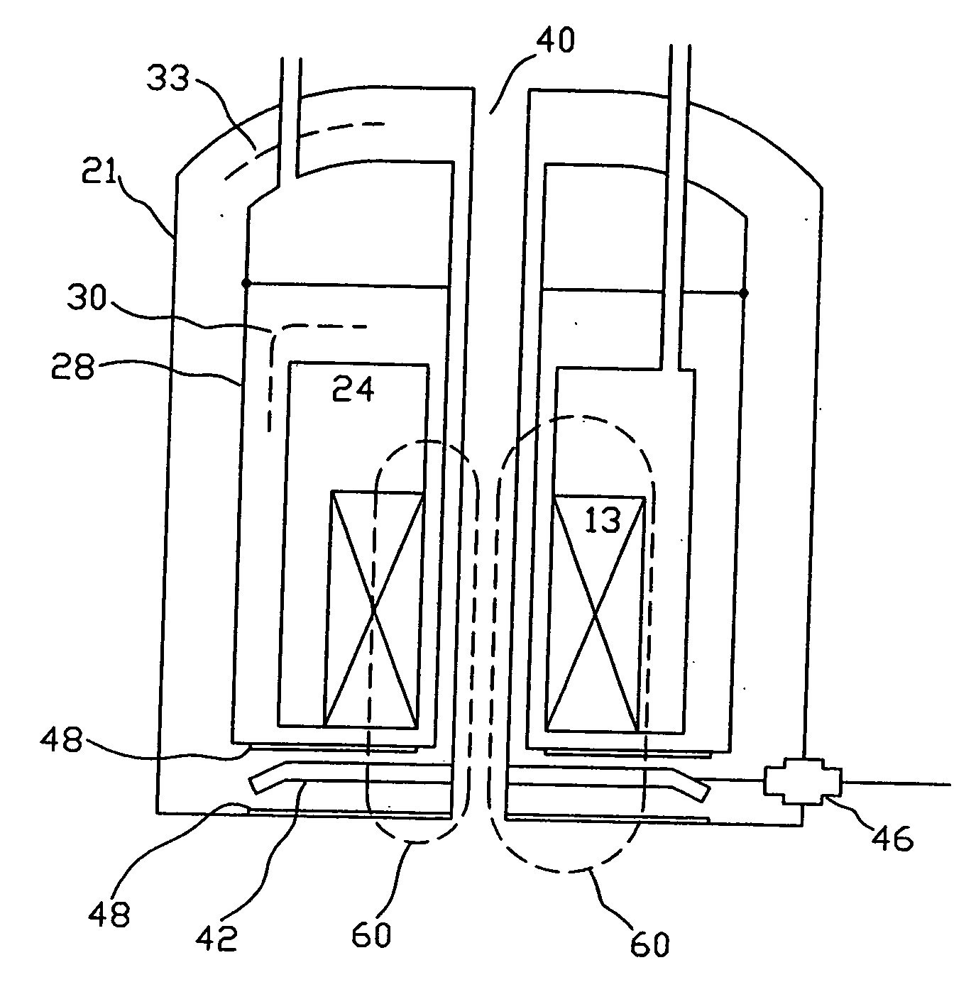
[0016]FIG. 1 includes a symbolic representation in section of a (simplified) conventional cryostat 20 in which there are located superconducting windings 13 forming a cryogenic magnet. The cryostat 20 includes heat shields 30 surrounding low temperature cryogen reservoir 24, an intermediate temperature cryogen reservoir 32 establishing constant temperature (heat shield) surface 28 and a higher intermediate temperature heat shield 33 surrounding all of the above components, enclosed within hermetically sealed housing 21. The entire interior communicating space of housing 21, exclusive of cryogen reservoirs 32 and 24, is evacuated to a pressure of the order of 10−4 torr at ambient temperature. When the cryostat is put into service by filling the cryogen reservoirs, most residual gases are condensed to a great degree and immobilized on the cold interior surfaces of the cryostat members, lowering the pressure to the order of 10−8 torr. While this results in satisfactory vacuum condition...


PUM


Abstract

Ion pumping modules without ion pump magnets are disposed within evacuated spaces located within the fringing fields of cryostatic housed high field magnets. Improved vacuum conditions are obtainable both within superconducting magnet cryostats and for evacuated auxiliary apparatus proximate the magnet cryostat, particularly where such auxiliary apparatus is sensitive to RF noise.

Description

FIELD OF THE INVENTION [0001] The invention relates to the field of vacuum ion pumps and particularly pertains to vacuum pumping applications with cryostat housed magnets. BACKGROUND OF THE INVENTION [0002] Vacuum ion pumps have been well studied over a period of more than 40 years, are the subject of a vast literature and have proven to be successful commercial products for maintenance of high vacuum. A review of such apparatus may be found in M. Hablanian, High Vacuum Technology: A Practical Guide, pp. 360-372, (Marcel Dekker, Inc., 1990). [0003] Although ion pumping apparatus is not limited to a particular geometry, the vacuum ion pump ordinarily includes an anode formed from an array of close packed, axially symmetric (tubular) metal elements and a cathode surface normal to the axis of the tubular array and spaced apart from the anode. (“Tubular” includes hexagonal, rectangular, circular, square and other cross sections for the purposes of this work.) The cathode(s) and anode(s)...

Claims


Application Information

Patent Timeline
IPC IPC(8): F04B37/02
CPCG01R33/30H01J41/12G01R33/3815
Inventor LUKENS, PETER
Owner VARIAN INC
Why Eureka
Try Eureka