Fuel cell and information terminal carrying the same

a technology of information terminal and fuel cell, which is applied in the direction of cell components, cell component details, electrochemical generators, etc., can solve the problems of large size of fuel cells, enlarged size, and inability to meet the needs of mobile power sources, etc., and achieves thin and light weight , the effect of sufficient outpu

Inactive Publication Date: 2006-03-02
HITACHI LTD
View PDF1 Cites 5 Cited by
  • Summary
  • Abstract
  • Description
  • Claims
  • Application Information

AI Technical Summary

Benefits of technology

[0014] One of the objects of the present invention is to provide a fuel cell having a separator for a thin type fuel cell that can generates a sufficient output and can be thinned and light-weighted.
[0015] Another object of the present invention is to provide a mobile information terminal with a fuel cell having a separator for a thin type fuel cell, which can realize more light-weight and thinner than the conventional fuel cells.
[0018] According to the fuel cell of embodiments of the present invention, it is possible to provide a small sized, compact fuel cell power source, which is particularly used for mobile phones, personal information terminals, notebook PCs, etc that have strongly demanded downsizing and thinning of power sources. The fuel cell of the invention has high energy density and is capable of continuous generation of power without charging operation, wherein fuel is easily supplied by exchanging a fuel cartridge tank.

Problems solved by technology

Since the polymer electrolyte type fuel cell generates electricity by using hydrogen, a hydrogen tank is needed, which leads to enlargement of its size.
Accordingly, the PEFC is not suitable as a power source for the mobiles.
If fuel cells are used for the notebook PCs or mobile phones for producing necessary power, the size of the fuel cells will become large.
Accordingly, the size of the fuel cell will become large, which is not suitable for the notebook PCs or mobile phones.
Conventional polymer electrolyte type fuel cells (PEFC) constituted as a stacked type fuel cell are difficult to be downsized; this type of fuel cells are not suitable for the notebook PCs or mobile phones.
However, though the conventional DMFCs, which are formed into panels are proper for thin type cells, it was difficult to obtain a high energy density.
However in the patent document No. 1, since a large number of separators 8 and cells I are stacked, it is difficult to obtain a thin-stacked fuel cell.
Therefore, the stacked fuel cell is not proper for a power source of PCs or mobile phones.

Method used


Image

  • Fuel cell and information terminal carrying the same
  • Fuel cell and information terminal carrying the same
  • Fuel cell and information terminal carrying the same

Examples


embodiment 1

[0036] In the following, the fuel cell according to the present invention will be explained in detail.

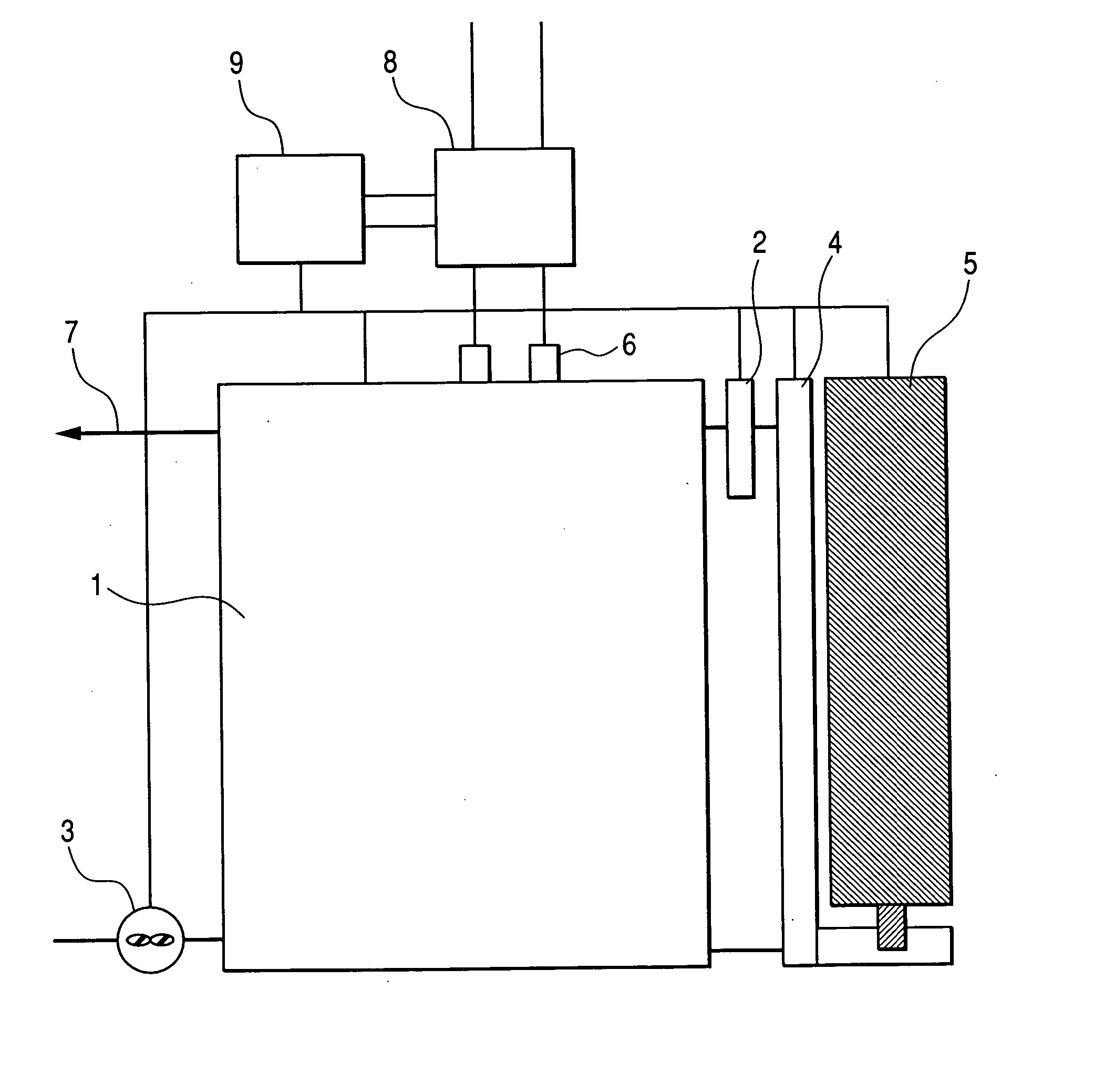
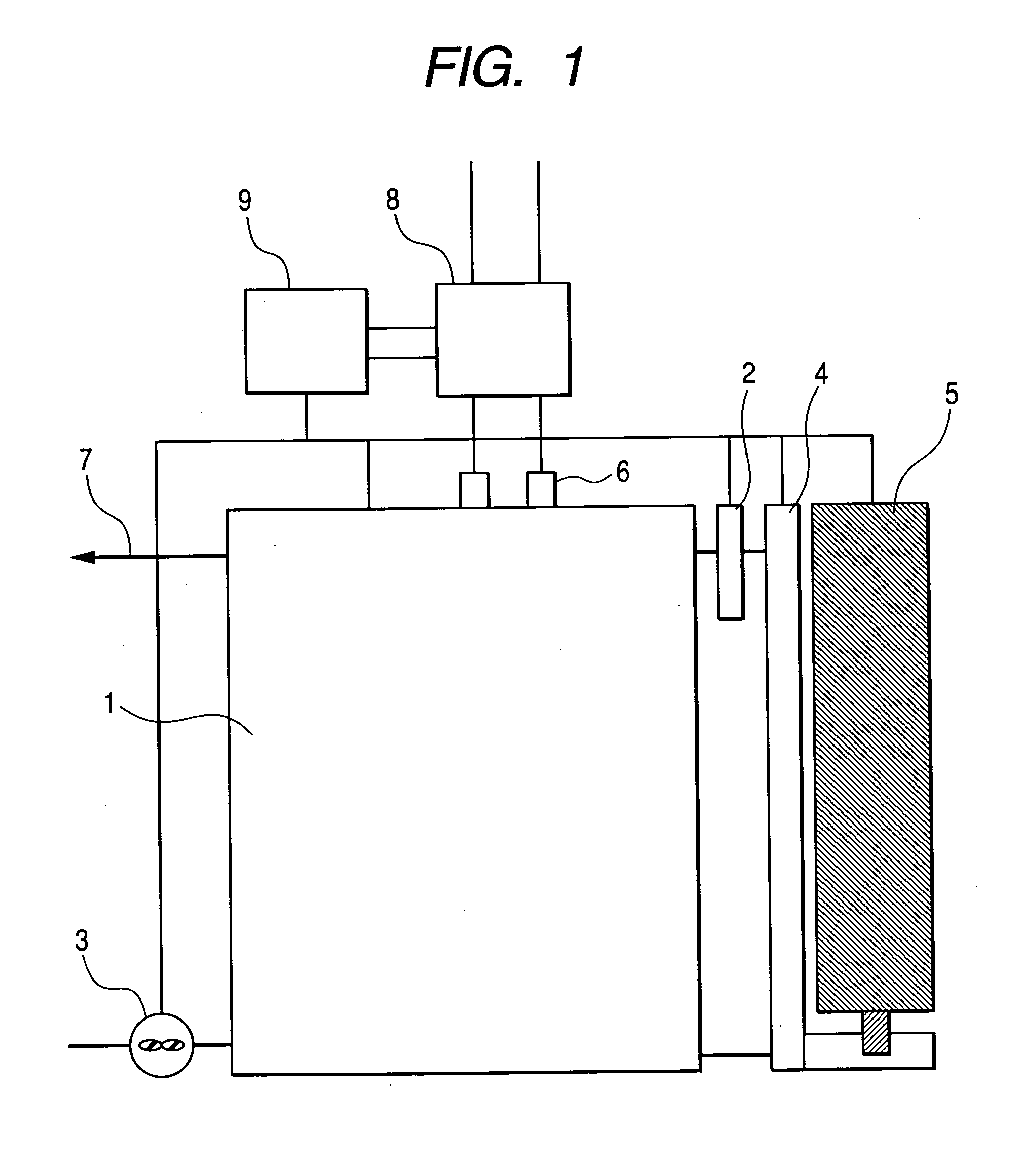
[0037]FIG. 1 shows a diagrammatic view of a fuel cell system according to the present invention. In this embodiment, a direct methanol type fuel cell, which employed a separator for a thin type fuel cell will be explained.

[0038] In FIG. 1, a power generation system using the fuel cell of the present invention comprises a fuel cell 1, a micro-pump 2 for circulating fuel in the fuel cell, a micro blower 3 for supplying air into the fuel cell, a fuel circulation tank 4, a fuel cartridge tank 5 and a gas discharge port 7. The micro-pump 2 sends out the fuel (methanol aqueous solution) stored in the fuel circulation tank 4 to the fuel cell at a constant pressure. The micro-blower 3 supplies air as an oxydant to the fuel cell at a constant pressure. The fuel circulation tank 4 stores the fuel to be supplied to the fuel cell with the micro-pump 2. The fuel cartridge tank 5 is an exchange...

embodiment 2

[0089] FIGS. 12(A) and 12(B) show a plan view and a cross sectional view of another embodiment of the present invention. In FIGS. 12 (A), 12(B), the bipolar plate 20 has no recessed portions where the current collectors are embedded. In this case, the bipolar plate 20 has four manifolds 11, the grooves 22 for distributing the fuel and the oxidant and through-holes 24 for screws for fixing the stack.

[0090] On the other hand, as shown in FIGS. 13(A), 13(B), a composite current collector 80 is constituted by current collectors 30 and the current collector frame 81. The separator 15 is constituted by the composite current collectors 80 and the bipolar plate 30 sandwiched between the current collectors 80.

[0091] In the DMFC comprising a fuel cell constituted by stacking unit cells each of which comprises the gasket, the cathode diffusion layer, MEA and the anode diffusion layer, the output power is monitored by the controller during the operation and stopping of the fuel cell, and the ...


PUM

PropertyMeasurementUnit
operating temperatureaaaaaaaaaa
voltageaaaaaaaaaa
voltageaaaaaaaaaa

Abstract

A fuel cell, which comprises a plurality of fuel cell units each comprising an anode for oxidizing fuel, a cathode for reducing oxygen, an membrane / electrode assembly sandwiched between the anode and the cathode, wherein the fuel cell units are arranged in a plane to constitute power generation unit, a plurality of the power generation unit being stacked by means of insulating plates. The disclosure is also concerned with an information terminal mounting the fuel cell.

Description

CLAIM OF PRIORITY [0001] This application claims of priority from Japanese application serial No. 2004-246073, filed on Aug. 26, 2004, the content of which is hereby incorporated by reference into this application. DESCRIPTION OF THE INVENTION [0002] 1. Field of the Invention [0003] The present invention relates to a fuel cell, and more particularly to a direct methanol fuel cell (DMFC), which is suitable for a power source of mobiles. The fuel cells are of a small thickness and high energy density. [0004] 2. Related Art [0005] Recently, portable information terminals such as notebook type personal computers, PDA (personal digital assistant), mobile phones have been developed and widely used. These information terminals have a technical target how to make its power source small and compact. [0006] There are two types of power sources for the mobiles, one of which is a polymer electrolyte type fuel cell (PEFC), constituted as a laminated type, and the other of which is a direct metha...

Claims


Application Information

Patent Timeline
Patent Type & Authority Applications(United States)
IPC IPC(8): H01M8/00H01M2/02
CPCH01M8/0204H01M8/023H01M8/0247H01M8/0263H01M8/04089H01M8/04186Y02E60/523H01M8/04619H01M8/04723H01M8/04731H01M8/04753H01M8/1011H01M8/246H01M8/04604Y02E60/50H01M8/2483H01M8/2428H01M8/242H01M8/2432H01M8/2418
Inventor KUBOTA, OSAMUKAMO, TOMOICHI
Owner HITACHI LTD
Why Eureka
Try Eureka