Automated building exterior cleaning apparatus

a technology for exterior surfaces and cleaning equipment, applied in the direction of cleaning using liquids, building repairs, instruments, etc., can solve the problems of preventing adoption and penetration into the marketplace, devices considered generally unsafe and impractical, and achieve the effect of reducing drippag

Inactive Publication Date: 2006-03-09
RAST RODGER H +1
View PDF12 Cites 131 Cited by
  • Summary
  • Abstract
  • Description
  • Claims
  • Application Information

AI Technical Summary

Benefits of technology

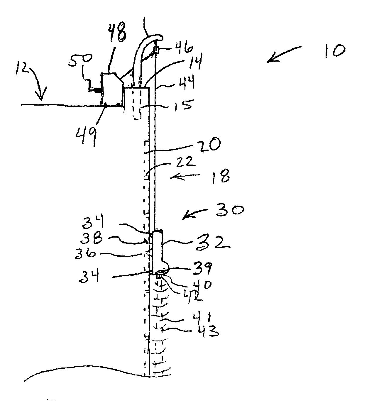
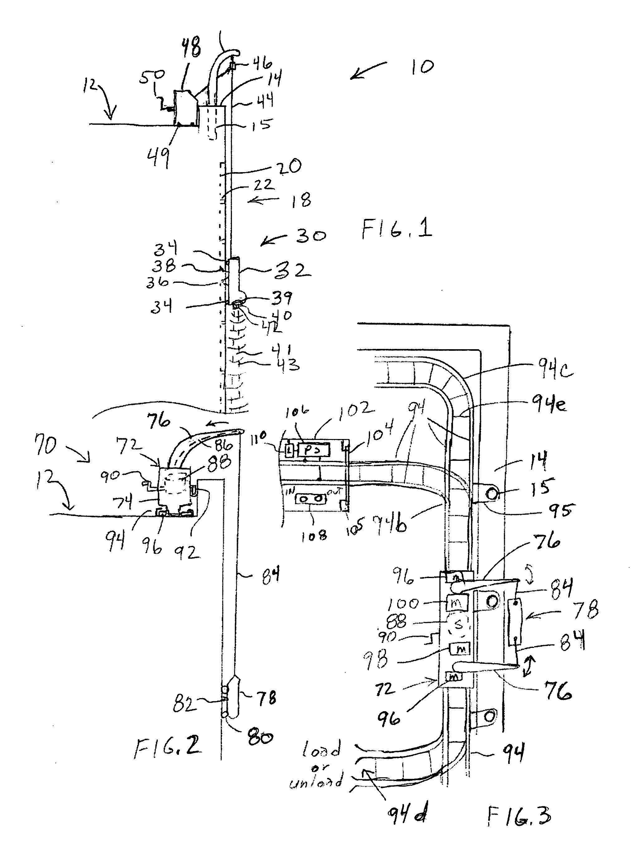
[0016] Another aspect of the present invention is to deploy a washing head from a movable platform which is easily and safely secured to the top of the building.
[0044] Another aspect of the present invention is to provide a washing head whose activity may be modulated in response to an image stream of surfaces and washing activity, preferably enhanced by controllable lighting (type, intensity, position, and / or direction).

Problems solved by technology

Automated window cleaning has been considered in the past, however, the devices considered were generally unsafe and impractical, preventing adoption and penetration into the marketplace.

Method used


Image

  • Automated building exterior cleaning apparatus
  • Automated building exterior cleaning apparatus
  • Automated building exterior cleaning apparatus

Examples


embodiment 850

[0370]FIG. 33 depicts a less preferably embodiment 850 for aftermarket, wherein the polymeric solar strip 852 is coupled to a combination connector 854 and charge circuit 856. configured for insertion into the charge receptacle of the phone. The strip is preferably rolled up and can be stored in the size of a 835mm canister. The circuit can be configured to maintain a proper charge level, typically a trickle charge. It is preferable that the voltage of the polymeric solar cell be sufficiently high under most conditions to provide for a positive charge flow. Charge circuit 856 may simple comprise a resistor, a resistor and diode, or it may have more sophisticated charging such as a ramp charging mechanism which allows increasing charge voltage for charge bursts at sufficient voltage. The use of step-up conversion would typically be too bulky for use in the preferred svelte package, although it could be done.

[0371] A weighted element 858 is provided at the opposing end to prevent inad...

embodiment 1610

[0469]FIG. 49 and 50 depicts an embodiment 1610 of a directed audio megaphone with a laser convergence indicator. To a base 1612 are coupled at least two ultrasonic transducer panels 1614, 1616, such as to joints or actuators 1618, 1620 which couple the panels to member 1622 utilized for providing structural rigidity and carrying the signals to the panels. It will be appreciated that joints 1618, 1620 can be utilized to allow the user to perform fully manual direction adjustments. It is preferred however that a more precise means of control be utilized. Consequently, actuators 1618, 1620 are preferred wherein they can be implemented using a mechanical control, such as a central control from which elongated members (i.e. wire, ribbon, stiff control rods, etc.) extend to each panel for controlling the direction. This embodiment in the figure, however, will depict the user of electrical actuators 1618, 1620 for controlling the direction of the ultrasonic transducers. A hand-held contro...


PUM


Abstract

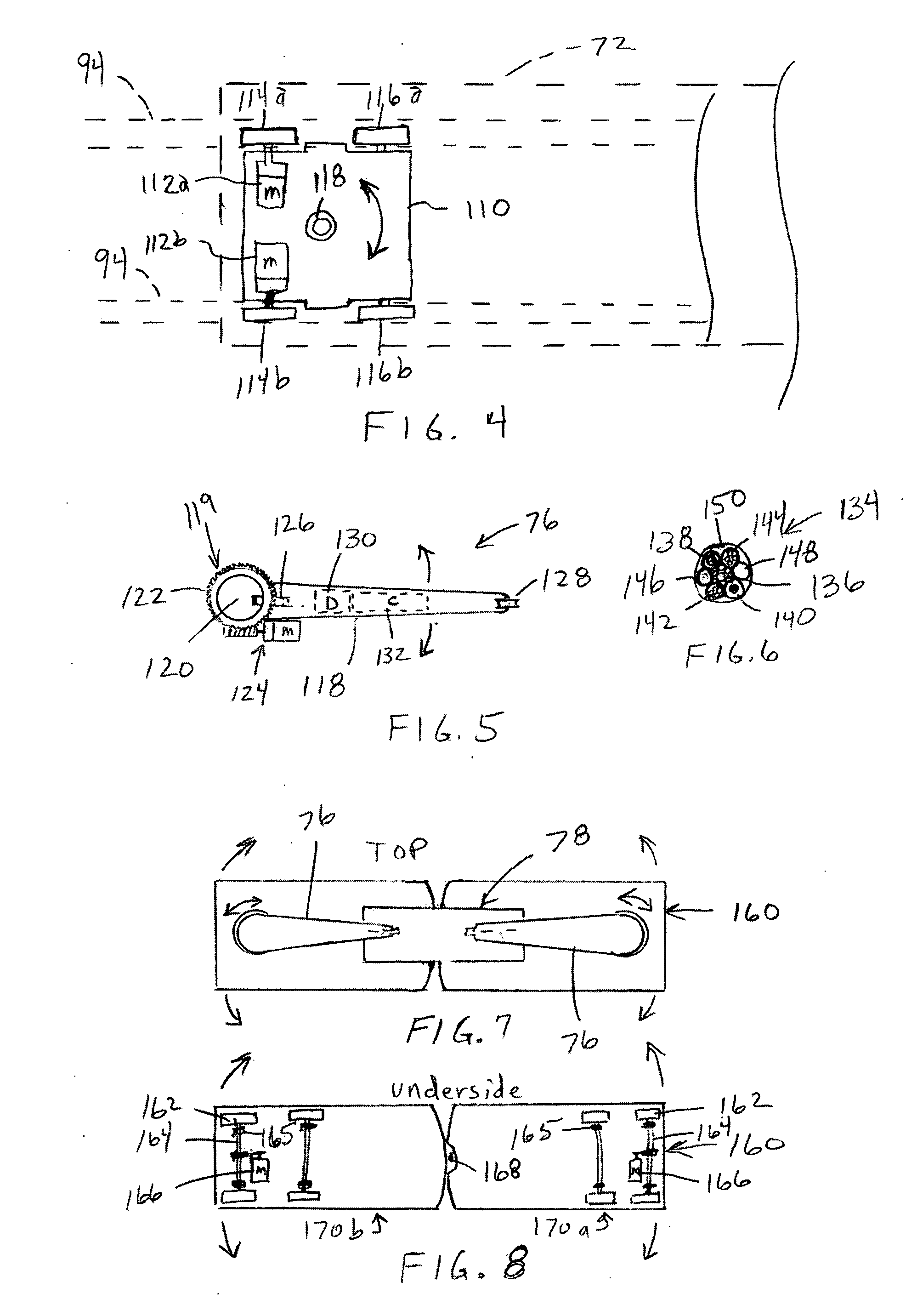
An automated exterior building cleaning system particularly well suited for cleaning the window exteriors on a high rise building. By way of example the system is deployed on a rooftop rail system traversed by a movable platform from which a washing head is deployed over the edges of the building and lowered on cables for cleaning the window surfaces and other building elements. The system is configured for remote monitoring and control and provides a number of novel elements and safety features.

Description

CROSS-REFERENCE TO RELATED APPLICATIONS [0001] This application claims priority from provisional patent application Ser. No. 60 / 608,789 filed Sep. 9, 2004 which is incorporated herein by reference and priority to which is claimed. [0002] This application is related to these copending applications, which are subject to a common assignment: Utility patent application docket KeyboardRAST070103 Ser. No. 10 / 612,777 filed Jul. 1, 2003; Provisional patent application entitled “Automated window washer” Ser. No. 60 / 394,160 filed Jul. 1, 2002; Utility patent application docket “TransportRAST070103” Ser. No. 10 / 612,225 filed Jul. 1, 2003; Utility patent application docket “Display_RAST092303” Ser. No. 10 / 670,432 filed Sep. 23, 2003; provisional patent application Ser. No. 60 / 413,199 filed Sep. 23, 2002; Utility patent application docket “DisplayRAST070103” Ser. No. 10 / 612,221 filed Jul. 1, 2003; Utility patent application docket “HardBLight” Ser. No. 09 / 730,327 filed Dec. 5, 2000; Provisional ...

Claims


Application Information

Patent Timeline
Patent Type & Authority Applications(United States)
IPC IPC(8): B08B3/00
CPCA47L1/02B08B3/04E04G23/002G05D1/0246G05D1/0274Y02B60/1242G05D2201/0203G06F1/3265H01L31/042Y02B10/12Y02E10/50G05D1/0278H02S20/30H02S30/20Y02D10/00Y02E70/30Y02B10/10H02S40/38H02S10/40
Inventor RAST, RODGER H.WIESNER, RICK MARTIN
Owner RAST RODGER H
Why Eureka
Try Eureka