
Apparatus for thermal imaging

a technology for thermal imaging and apparatus, applied in the direction of optical radiation measurement, instruments, measurement devices, etc., can solve the problems of furnace shut down, increased the possibility of premature failure, and reduced life,

Inactive Publication Date: 2006-03-09
LUMASENSE TECH HLDG
View PDF24 Cites 38 Cited by
  • Summary
  • Abstract
  • Description
  • Claims
  • Application Information

AI Technical Summary

Benefits of technology

[0022] Towards the accomplishment of these and other objectives and advantages which will become apparent from a reading of this specification taken together with the accompanying drawings there is provided a device for thermal imaging of target surface(s) having different temperatures within a range of temperatures of interest between a high and low temperature of −40° C. to 2000° C. The thermal imaging takes place through intervening media having a known transmission wavelength. The target surface(s) have a known absorptive wavelength.

Problems solved by technology

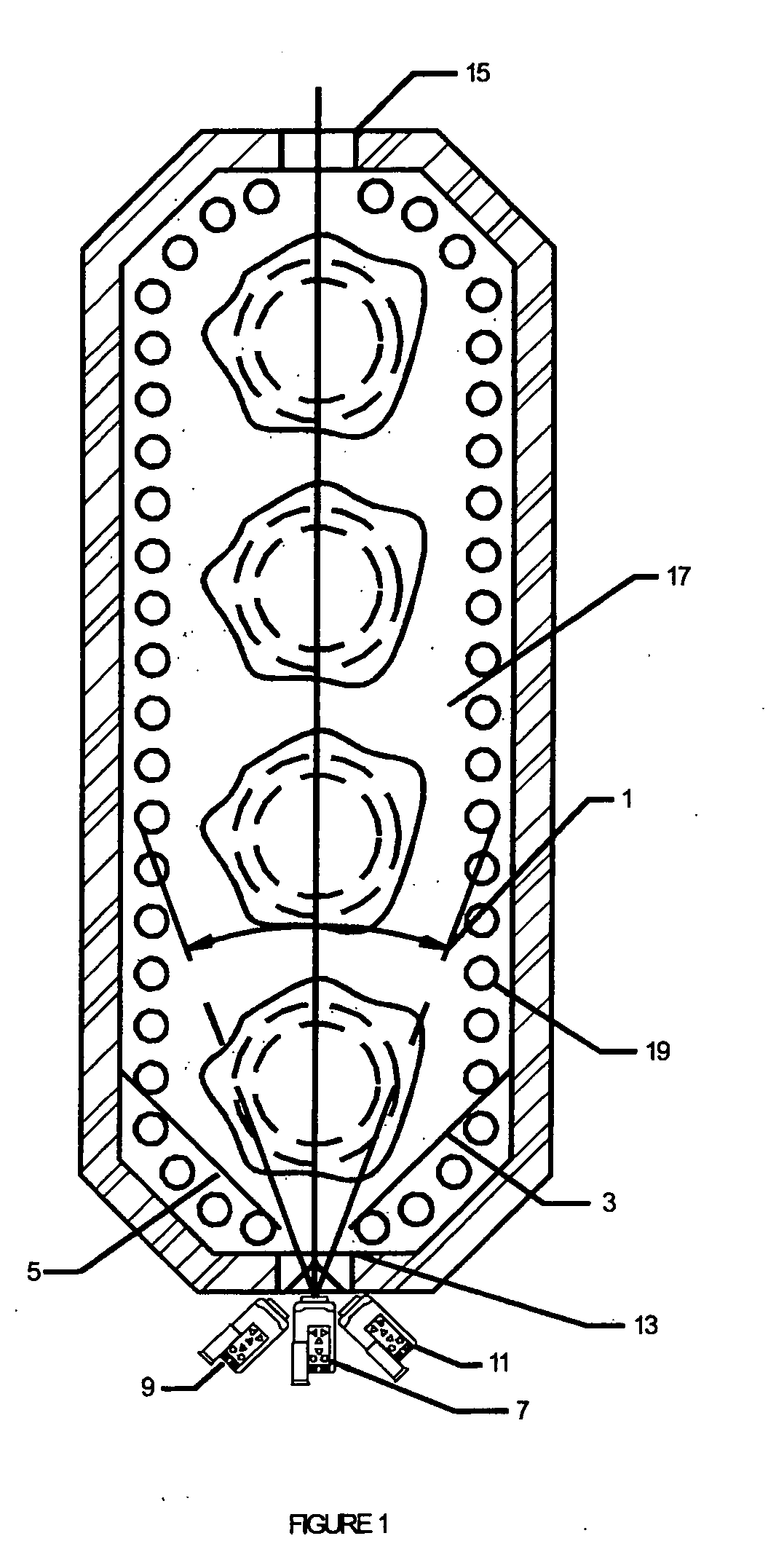
The temperature range in these processes varies from 400 to 1200° C. It is widely recognized that operation of furnace tubes above their creep-rupture design temperature, for example in ethylene plants, results in diminished lifetimes and increases the prospects for premature failures.
Any failure of the tubes results in very expensive repair costs and furnace shut downs.
In addition, temperatures often adversely affect productivity or yield of desired product.
For example a 10° C. temperature difference from desired temperature at the coil output of a large ethylene plant can result in hundreds of thousands of dollars of revenue loss per year.
Such a loss is caused by a less than desired conversion of the feedstock.
When operating at a slightly higher temperature than optimum, overcaking and increased coke formation inside of the tubes results.
Large uncertainties in the tube surface temperatures are unacceptable if the process is to operate under nearly optimized conditions with any degree of confidence.
Power utilities are becoming more cost conscious as the result of deregulation.
However, thermocouple installations are unreliable for extended operation because of the rapid drift in their calibration; and, deterioration of the protective materials in the furnace atmosphere.
In addition the number of thermocouples installed is limited due to the complexity which results in the associated wiring and instrumentation.
It is nearly impossible to identify the exact location of tube coking by the thermocouple method.
These conventional, single point, portable radiation thermometers have one serious shortcoming, i.e., it is nearly impossible to expect someone to measure all the tubes across the entire length or height of the furnace.
Operator fatigue and boredom will eventually result in the deterioration of the quality of the reported data.
However, the matter of establishing absolute temperature levels on tubes is quite another matter.
Firstly, in order for a cryocooler to reach sufficiently low cryogenic temperatures it takes several minutes.
A normal failure mode is the leaking of helium gas through the seals.
Besides being costly, repairs normally are associated with long delays due either to spare parts' shortages or the limited number of repair people with the necessary level of expertise.
Further, the battery life is mostly consumed in keeping the detector cooled.
This adds to the inconvenience and poses a threat to the safety of the operators, since operators must image the interior of these furnaces from narrow catwalks through hot view ports several stories high.
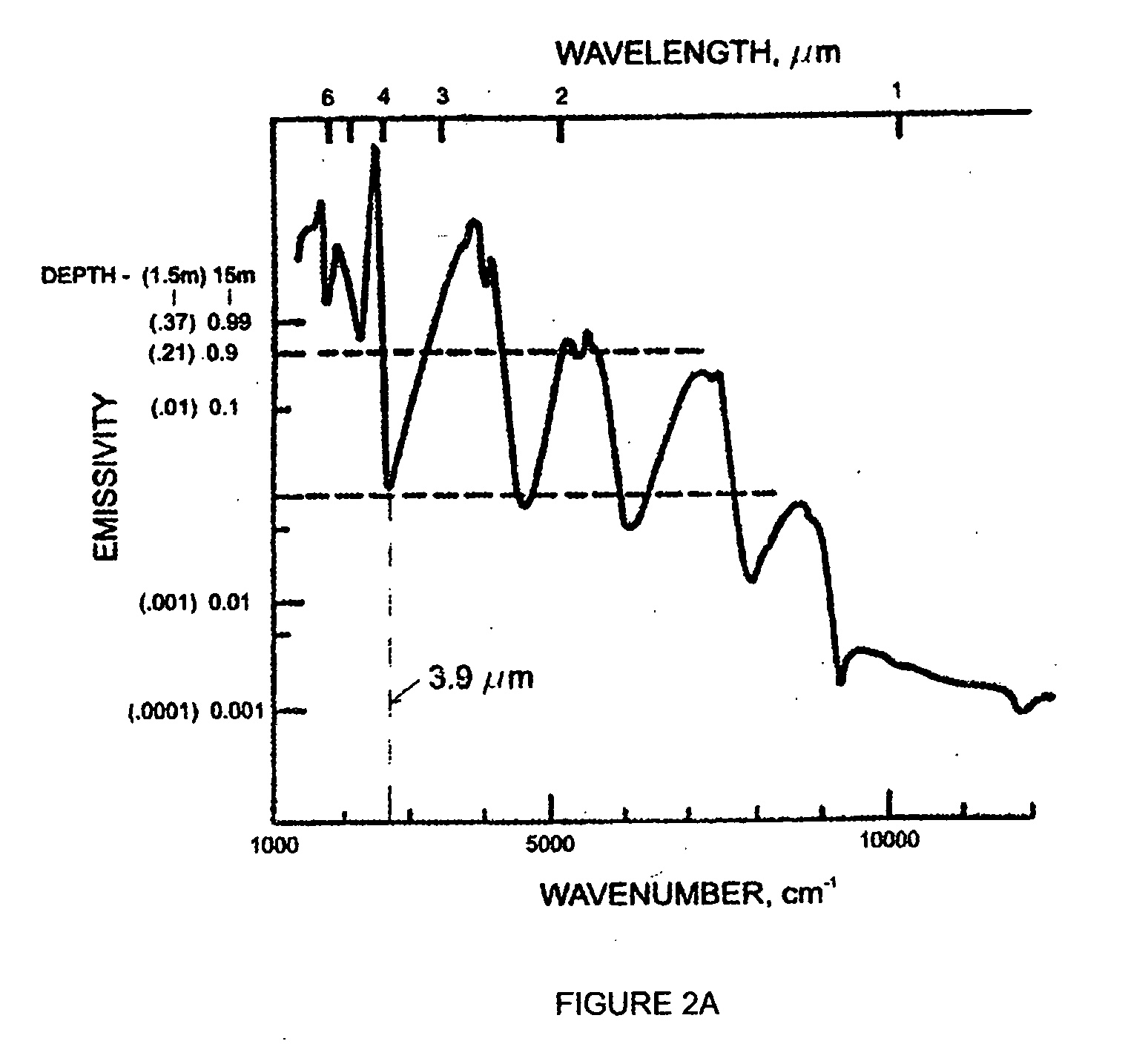
Further, these photon detectors are effectively limited, again, to the spectral band of 3 to 5 um.
As such, they are not useful in detecting “lower” temperatures, for example, in the range of −40 to 200° C., and particularly outdoors, during the day, in sunlight, which, due to the influence of the sun, a powerful source of radiation energy at 3 to 5 um, precludes their use.
These lower temperatures can occur at other points in petrochemical-related processes and can also be very critical.

Method used


Image

  • Apparatus for thermal imaging
  • Apparatus for thermal imaging
  • Apparatus for thermal imaging

Examples


Embodiment Construction

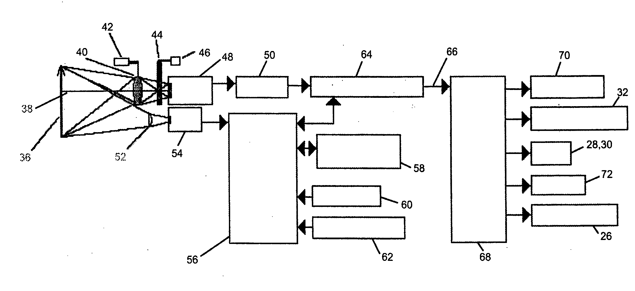
[0052] Referring now to the drawings wherein the same reference numbers are used in various figures to identify the same item, in FIGS. 3, 3A and 3B, a version of the Assignee's (Applicant's) Model 7200 V, thermal imager modified to implement the present invention is depicted. The improved device for thermal imaging of target surfaces includes a housing 12 having an opening 14 through which the infrared rays emanating from the target surface(s) are received. The improved device is an extremely light weight high-performance, IR camera which is designed for comfortable, one-handed point-and-shot operation. It uses an intuitive key pad located on the top of the imager which includes cursor controls 16, focus controls 18, menu selection key 20 and mode selection key 22. The menu selection key 20 allows the operator to identify the temperature range to be viewed.

[0053] Battery power is supplied upon activation of power switch 24 (FIG. 3B). Memory card slot means 26 is provided to enable...


PUM


Abstract

A device for thermal imaging of target surfaces includes a housing (12) with an opening (14) for directing incident infrared rays along an optical path through an optical assembly (40) optimized to have a spectral band width of 3 to 14 um, onto a UFPA detector (48) having a spectral transmission window (84) which has a bandwidth 3 to 14 um sufficient to pass all infrared rays of interest over a broad temperature range. Filter means (44) including at least two filters (78, 80), having a band width in the ranges of 3 to 8 um and 8 to 14 um, respectively, allow for the placement of either specialized IR filter in the optical path so as to attenuate and / or pass certain wavelengths of the infrared rays depending on the specific application in a broad range between −40° C. to 2000° C. The device allows for thermal imaging even in daytime applications in sunlight.

Description

FIELD OF THE INVENTION [0001] This invention relates to an apparatus for providing thermal images in unique situations, for example the thermal imaging of the wall surface of tubes used in direct-fired, process heaters, and to such an apparatus which further allows for temperature measurements associated with conventional, predictive preventive maintenance PPM applications involved with the industrial process, or otherwise at the facility, as the user identifies and selects. BACKGROUND [0002] There are classes of applications in petrochemical and power utility industries that involve the thermal imaging and absolute temperature measurement of wall-tube surfaces in direct fired process heaters under production conditions. The temperature range in these processes varies from 400 to 1200° C. It is widely recognized that operation of furnace tubes above their creep-rupture design temperature, for example in ethylene plants, results in diminished lifetimes and increases the prospects for...

Claims


Application Information

Patent Timeline
Patent Type & Authority Applications(United States)
IPC IPC(8): G01J5/02
CPCG01J5/0044G01J5/02G01J5/025G01J5/0265G01J2005/0077G01J5/08G01J5/0862G01J5/602G01J5/04G01J5/0802
Inventor IRANI, KEIKHOSROW
Owner LUMASENSE TECH HLDG
Learn More