Aligning drive mechanism and positioning apparatus having this mechanism

a technology of aligning drive mechanism and positioning apparatus, which is applied in the direction of machine support, bearing unit rigid support, manufacturing tools, etc., can solve the problems of increasing sliding gap, tilting of clamp rod, and inability to accurately guide clamp rod, etc., and achieves high accuracy

Inactive Publication Date: 2006-03-09
KOSMEK LTD (JP)
View PDF6 Cites 40 Cited by
  • Summary
  • Abstract
  • Description
  • Claims
  • Application Information

AI Technical Summary

Benefits of technology

[0051] In this case, the gap for both expansion and contraction of the annular collet can be automatically cleaned up, by which the annular collet can be expandable and contractible with high accuracy and smoothly.

Problems solved by technology

Therefore, the clamp rod tilts due to the fitting gap during clamping operation of the clamp rod.
As a result, the clamp rod cannot be accurately guided.
However, any sliding gap cannot be omitted between each of the sliding portions and the housing, which contains a problem that the sliding gap could increase due to machining errors.

Method used


Image

  • Aligning drive mechanism and positioning apparatus having this mechanism
  • Aligning drive mechanism and positioning apparatus having this mechanism
  • Aligning drive mechanism and positioning apparatus having this mechanism

Examples


first embodiment

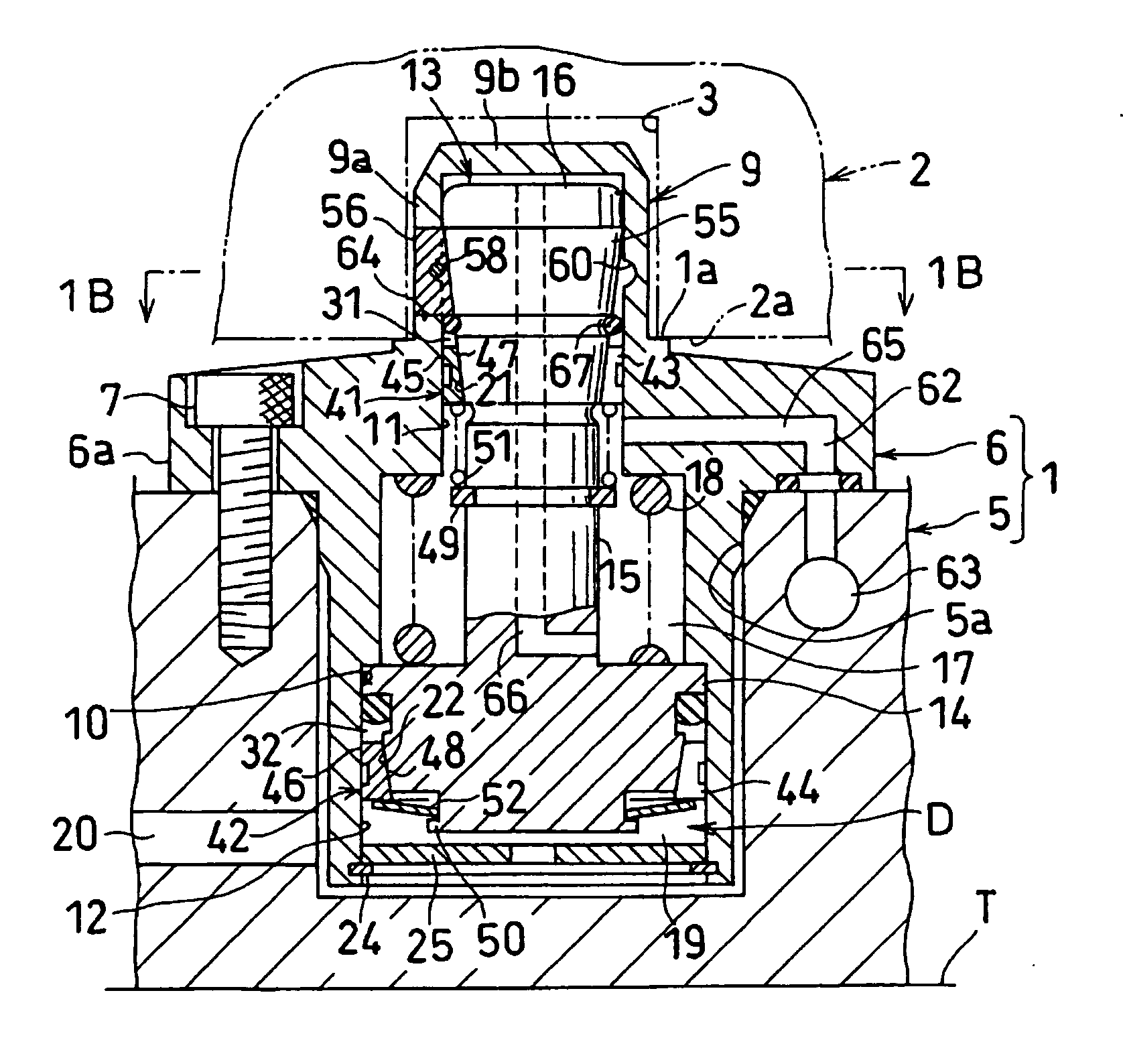
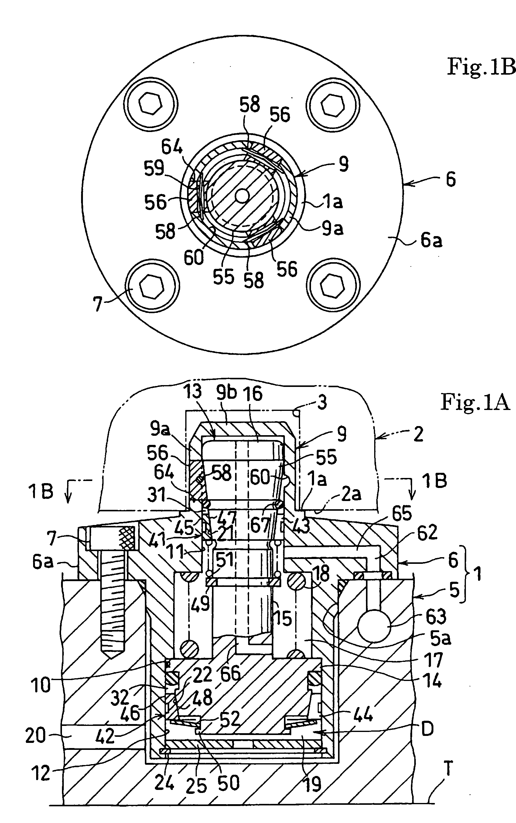
[0070]FIG. 1A and FIG. 1B show the present invention, and illustrate a positioning apparatus having an aligning drive mechanism applied to a pallet system. FIG. 1A is an elevational cross-sectional view showing the positioning apparatus in a released state. FIG. 1B is a cross-sectional view indicated by the arrow 1B-1B in FIG. 1A.

[0071] In this embodiment, on a table T of a machine tool is placed a reference block 1, a support surface 1a is adapted to receive a supported surface 2a of a work pallet 2 as a movable block. In the supported surface 2a are opened a plurality of positioning holes 3 formed with circular straight holes. Herein, only one of the positioning holes 3 is illustrated.

[0072] The reference block 1 comprises a base plate 5 fixed to the table T and a housing 6 fixed to the base plate 5. Into an installation hole 5a opened in the base plate 5 is accurately fitted the housing 6, and a flange 6a of the housing 6 is fixed to a peripheral wall of the installation hole 5a...

second embodiment

[0128] The positioning apparatus of the second embodiment operates as follows.

[0129] When the releasing state illustrated in FIG. 4A is switched into a locking state, pressurized oil is supplied to the lock chamber 17. Then, first, the output member 13 descends, by which the wedge surface 55 pushes the pressing member 56 radially outward, and the pressing portion 74 of the pressing member 56 engages with the positioning hole 3 in a bitten state. At the same time as this positioning, the annular plug 9 descends against the coned disc spring 72, by which the pressing member 56, which is in a bitten state, strongly presses the work pallet 2 against the reference block 1. Therefore, the clamp means (not shown) described in the explanation of the first embodiment may be omitted.

[0130] It is noted that the positioning apparatus is provided with a seating confirmation means. That is, a detection nozzle hole 78 is opened in the support surface 1a, and compressed air for detecting is suppli...

third embodiment

[0135]FIG. 5 and FIG. 6 show the present invention. FIG. 5 is a view similar to FIG. 4A. FIG. 6 is an end view indicated by the arrow 6-6 in FIG. 5, which is similar to FIG. 4B.

[0136] This third embodiment is different from the second embodiment (illustrated in FIG. 4A and FIG. 4B) in the following points.

[0137] The movable block 2 is composed of a work piece, and the positioning hole 3 is formed with a through hole.

[0138] The annular plug 9 is supported on the housing 6 via the annular bolt 73 vertically movably, and fixed by a guide pin 80 so as not to rotate. The advancing means 72, which presses the annular plug 9 upward, is composed of a compressed coil spring, which is installed between the ceiling wall 9b of the annular plug 9 and the output portion 16.

[0139] The first aligning space 31 is formed in such a manner as to narrow downward, the straight surface 45 on the outer periphery of the first shuttle member 41 is supported on the first guide hole 11 vertically slidably, ...


PUM


Abstract

A housing (6) is provided in a reference block (1). An annular plug (9), which is to be inserted into a positioning hole (3) of a work pallet (2), is projected upward from the housing (6). An output member (13) is inserted into a guide hole (10) of the housing (6) vertically movably. An upper end of the output member (13) is inserted into the annular plug (9), and a plurality of pressing members (56) are supported on a peripheral wall (9a) of the annular plug (9) radially movably. An annular aligning space (31) is formed between a guided portion (21) of the output member (13) and the guide hole (10). A shuttle member (41), which is diametrically expandable and contractible, is inserted into the aligning space (31). The shuttle member (41) is urged upward by a spring (51).

Description

TECHNICAL FIELD [0001] The present invention relates to a mechanism which drives an output member such as a clamp rod and the like while aligning, and a positioning apparatus having this mechanism, more specifically, to a technique preferable for positioning a clamp for fixing a work piece or a metal mold or the like, or for positioning a work pallet or the like. BACKGROUND OF THE INVENTION [0002] This kind of driving mechanism is described in U.S. Pat. No. 5,820,118 for example. This driving mechanism in the prior art is composed as follows. [0003] A clamp rod is inserted into a housing, a middle high portion of the clamp rod is supported vertically movably on an upper wall of the housing, and a piston provided at a lower portion of the clamp rod is supported on a barrel portion of the housing vertically movably. [0004] The above-mentioned prior art contains several problems. [0005] That is, to move the piston smoothly, a relatively large fitting gap is required between an outer pe...

Claims


Application Information

Patent Timeline
Patent Type & Authority Applications(United States)
IPC IPC(8): B23Q3/00B23B31/40B23Q1/00B23Q3/06B23Q3/18B23Q7/14F16C27/06F16M7/00
CPCB23B31/402F16M7/00B23Q1/009B23B31/4053
Inventor YONEZAWA, KEITAROSHIRAKAWA, TSUTOMUHARUNA, YOSUKE
Owner KOSMEK LTD (JP)
Why Eureka
Try Eureka