Capacitance detection circuit and capacitance detection method

a capacitance detection and capacitance detection technology, applied in the direction of resistance/reactance/impedence, measurement devices, instruments, etc., can solve the problems of bringing the noise of the piece to be detected to a level, and the capacitance measurement of the capacitance detection element cannot be accurately performed, so as to achieve high accuracy and small capacitance value. , the effect of high resolution

Inactive Publication Date: 2006-03-09
ALPS ALPINE CO LTD
View PDF3 Cites 88 Cited by
  • Summary
  • Abstract
  • Description
  • Claims
  • Application Information

AI Technical Summary

Benefits of technology

[0023] With this configuration, in the capacitance detection circuit in accordance with the present invention, variations of the reference potential depending on the location where the reference electrode is disposed can be reduced. Thus, even if the piece to be detected contacts any reference electrode, the reference potential can be used as a reference potential for all the detection electrodes on the sensor plane.
[0024] Since the fingerprint sensor in accordance with the present invention has a capacitance detection circuit described in the foregoing, it is possible to detect the capacitance change of the detection electrode and possible to detect the shape of a fingerprint with high accuracy.
[0025] As described in the foregoing, according to the capacitance detection circuit in accordance with the present invention, both the configuration of a reference electrode for detecting the electrical potential of a piece to be detected as a reference potential and the configuration for separating the capacitance of the detection electrode in the driven detection wiring...

Problems solved by technology

As a result, if the sensitivity of the charge amplifier circuit is increased to detect a very small capacitance change, the signal output from the charge amplifier circuit changes due to the voltage value due to noise that is mixed in via the parasitic capacitance Cn from the piece to be detected, presenting the drawback that the measurement of the capacitance of the ...

Method used


Image

  • Capacitance detection circuit and capacitance detection method
  • Capacitance detection circuit and capacitance detection method
  • Capacitance detection circuit and capacitance detection method

Examples


Embodiment Construction

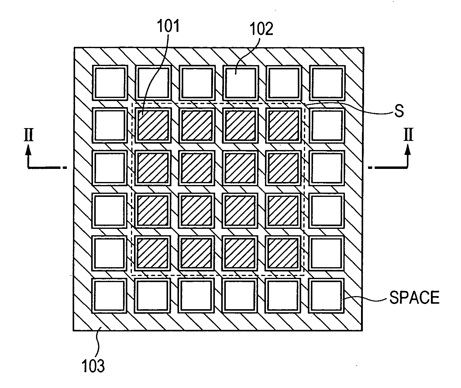
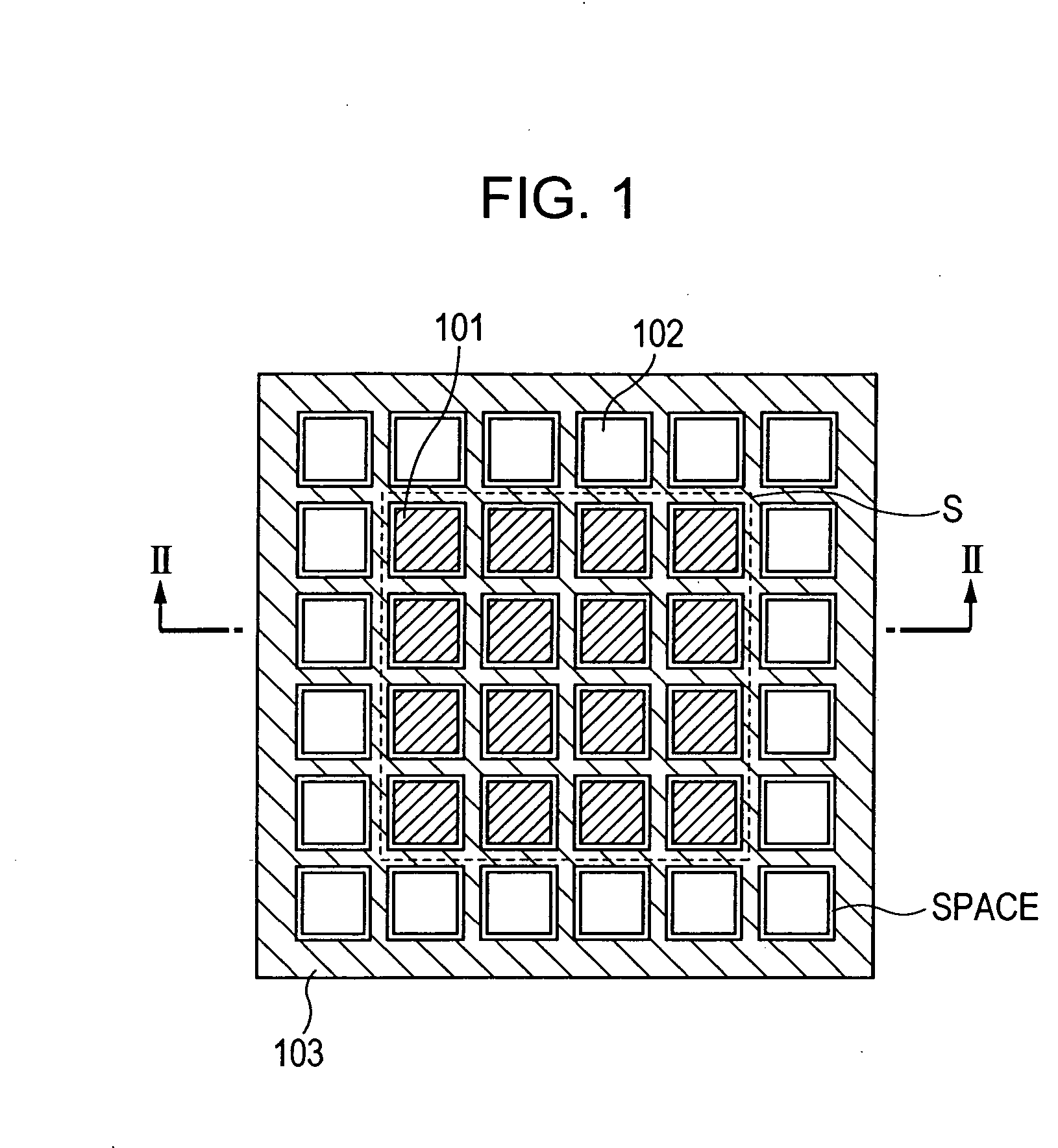
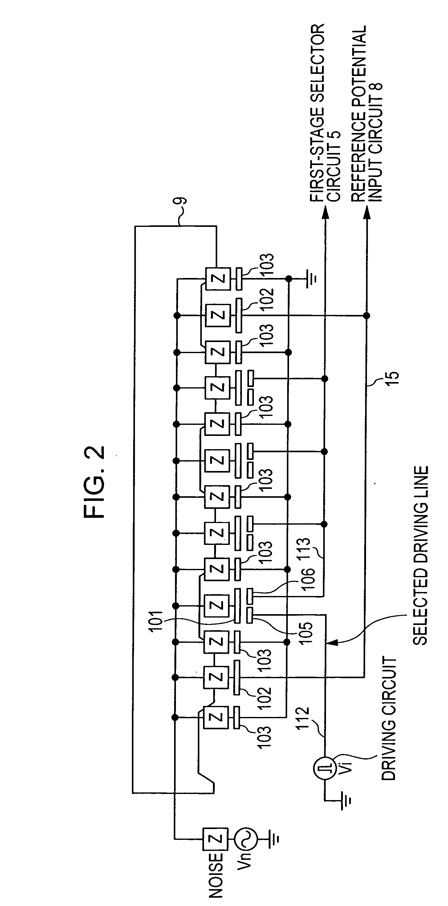
[0041] A capacitance detection circuit of the present invention is a capacitance detection circuit in which detection wirings are arranged in such a manner as to intersect a plurality of driving wirings, detection electrodes forming capacitances between the driving wirings and the detection wirings that intersect each other are formed within a sensor plane, and a capacitance change of the detection electrode, which changes due to a piece to be detected, is detected as a voltage value, the capacitance detection circuit including: column wiring driving means for driving the driving wirings; detection wiring selection means for selecting predetermined detection wiring from among a plurality of detection wirings; a reference electrode arranged in the vicinity of the detection electrode, the reference electrode detecting the electrical potential of the piece to be detected as a reference potential; and a capacitance computation section for determining a voltage value corresponding to the...


PUM


Abstract

A capacitance detection circuit in which detection wirings are arranged in such a manner as to intersect a plurality of driving wirings, and detection electrodes forming capacitances between the driving wirings and the detection wiring that intersect each other are formed within a sensor plane includes a column wiring driving device for driving the driving wirings; a detection wiring selection device for selecting predetermined detection wiring from among a plurality of detection wirings; a reference electrode arranged in the vicinity of the detection electrode, the reference electrode detecting the electrical potential of the piece to be detected as a reference potential; and a capacitance computation section for determining a voltage value corresponding to the capacitance change on the basis of the reference potential and the detection potential determined from the electrical current corresponding to the capacitance of the detection electrode.

Description

BACKGROUND OF THE INVENTION [0001] 1. Field of the Invention [0002] The present invention relates to a capacitance detection circuit for detecting irregularities of a piece to be detected, such as a fingerprint of a finger, and to a capacitance detection method for use therewith. [0003] 2. Description of the Related Art [0004] Hitherto, as capacitance detecting sensors for detecting irregularities of a piece to be detected, capacitance detecting sensors for detecting an electrostatic capacitance between detection electrodes arranged in an array and a piece to be detected and for measuring a change in the capacitance by using a peripheral circuit have been proposed. For this capacitance detecting sensor, in a peripheral circuit for performing capacitance detection, for example, a charge amplifier circuit shown in FIG. 13 is often used (refer to, for example, Japanese Unexamined Patent Application Publication No. 2001-46359). [0005] The charge amplifier circuit has a function for conv...

Claims


Application Information

Patent Timeline
IPC IPC(8): G01R27/26
CPCG01D5/2405G01D5/24
Inventor UMEDA, YUICHI
Owner ALPS ALPINE CO LTD
Why Eureka
Try Eureka