

Confocal microscope
- Summary
- Abstract
- Description
- Claims
- Application Information
AI Technical Summary
Benefits of technology
Problems solved by technology
Method used
Image

Examples
first embodiment
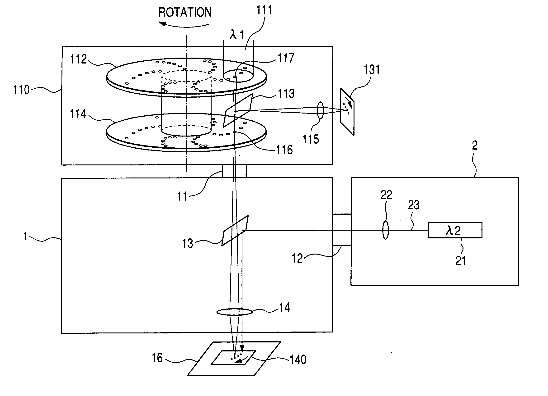
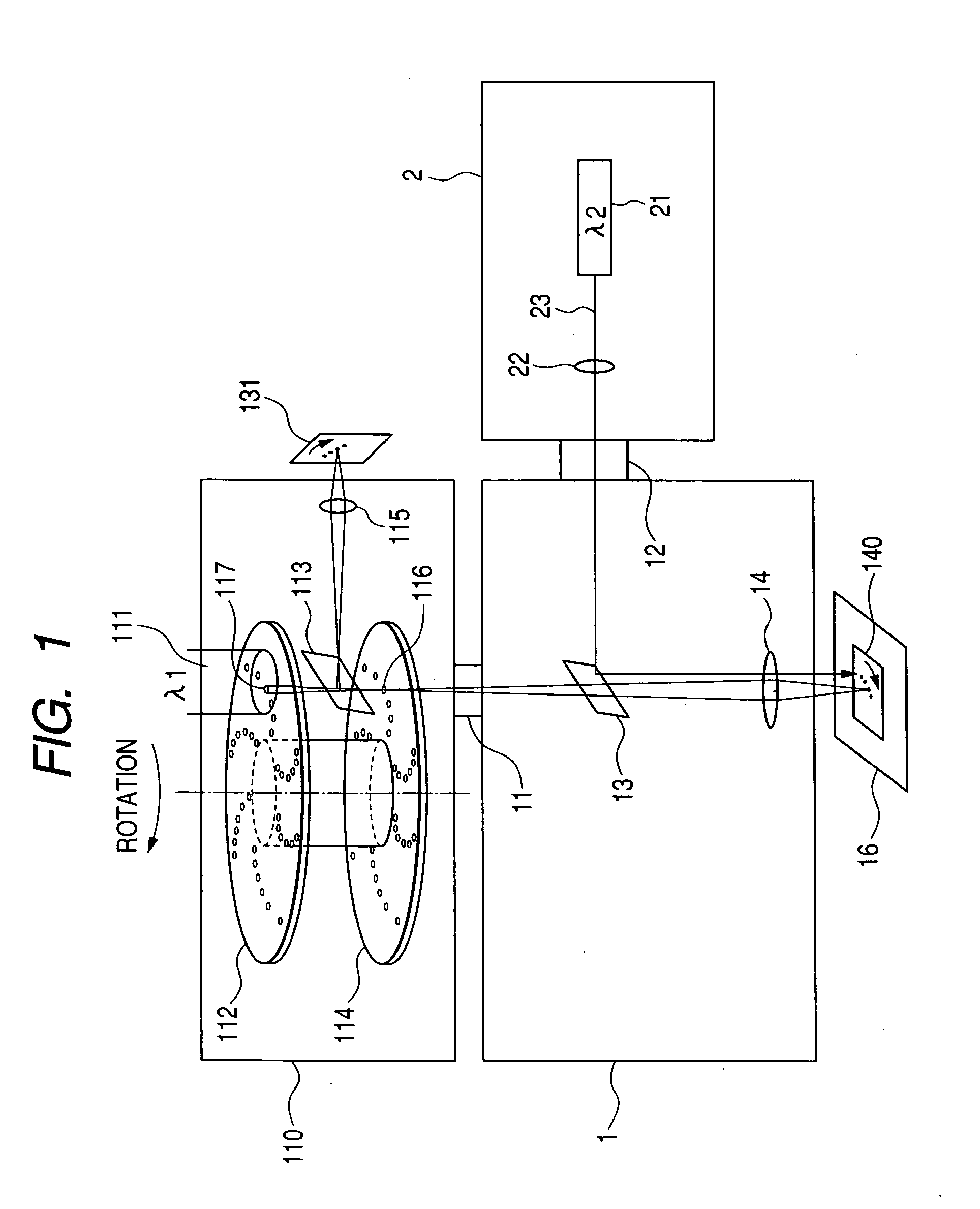
[0029] Embodiments of the invention will be explained in details in reference to the drawings as follows. FIG. 1 is a configuration view showing a confocal microscope according to the invention. Constituent elements similar to those of the drawings previously shown are attached with similar notations, and an explanation of the elements will be omitted.
[0030] In FIG. 1, a first port 11 of the microscope 1 is attached with the confocal scanner 110 to constitute the confocal microscope for irradiating the laser beam 111 (first laser beam) having a wavelength of λ1 to the sample 140. The laser beam 111 entering the microscope 1 is converged to the sample 140 of a cell or the like on a stage 16 by an object lens 14 after transmitting through a dichroic mirror 13. The sample 140 emits fluorescence by irradiation of the laser beam 111. A fluorescence signal emitted from the sample 140 passes through the object lens 14 again, transmits through the dichroic mirror 13, and is imaged on the im...
second embodiment
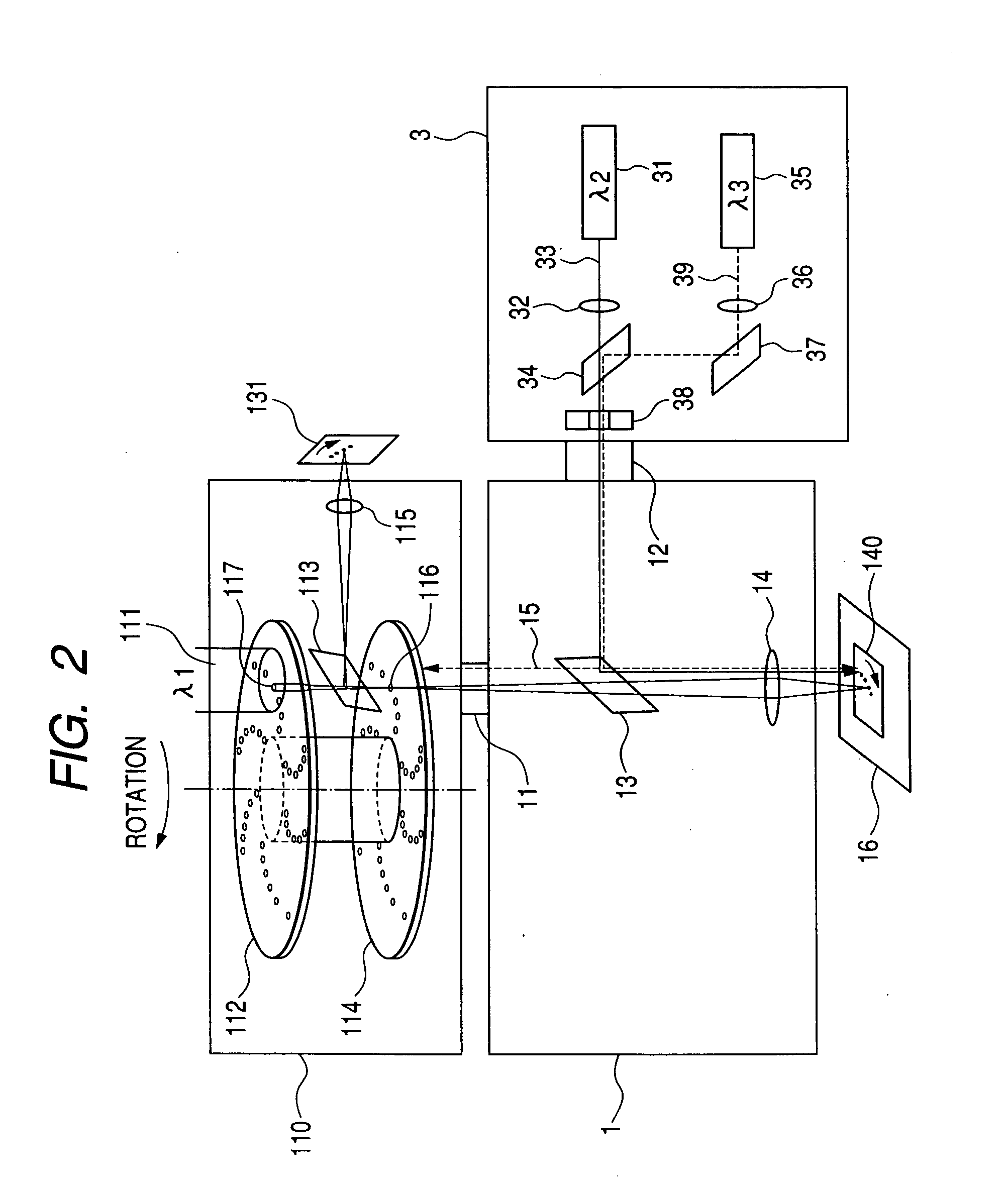
[0035]FIG. 2 is a configuration view showing a second embodiment according to the invention. Constituent elements similar to those of the drawings previously shown are attached with similar notations, and an explanation of the elements will be omitted.
[0036] In FIG. 2, the first port 11 of the microscope 1 is attached with the confocal scanner 110 to constitute the confocal microscope for irradiating the laser beam 111 having a wavelength of λ1 to the sample 140. The laser beam 111 entering inside the microscope 1 is converged to the sample 140 on the stage 16 by the object lens 14 after transmitting through the dichroic mirror 13. The sample 140 emits fluorescence by irradiation of the laser beam 111. A fluorescence signal emitted from the sample 140 passes through the object lens 14 again, transmits through the dichroic mirror 13, and is imaged on the image scanner 131 via the confocal scanner 110 similar to the related art.
[0037] The second port 12 of the microscope 1 is attache...
third embodiment
[0042]FIG. 3 is a configuration view showing a third embodiment according to the invention. Constituent elements similar to those of the drawings previously shown are attached with similar notations, and an explanation of the elements will be omitted.
[0043] In FIG. 3, configuration of the confocal scanner 110 and the microscope 1 are similar to those shown in FIG. 2 previously shown.
[0044] The second port 12 of the microscope 1 is attached with a laser beam output section 4. The laser beam output section 4 is provided with the laser beam sources 31, 35, the collimator lenses 32, 36, the dichroic mirror 34, the total reflection mirror 37, and a scanning section 40.
[0045] Configuration and operation of the laser beam sources 31, 35, the collimator lenses 32, 36, the dichroic mirror 34, and the total reflection mirror 37 are similar to those of the second embodiment shown in FIG. 2. The scanning section 40 is added to the configuration.
[0046] The scanning section 40 constitutes a sc...
PUM
 Abstract
Description
Claims
Application Information