Liquid cooled heat sink with cold plate retention mechanism

a technology of cooling sink and cooling plate, which is applied in the direction of power cables, lighting and heating apparatus, cables, etc., can solve the problems of increasing the power to be dispersed by semiconductor devices, the thermal conductivity of available materials becomes too low, and the power density emerging from semiconductor devices will be so high, so as to improve thermal transfer

Active Publication Date: 2006-03-09
THERMAL
View PDF26 Cites 48 Cited by
  • Summary
  • Abstract
  • Description
  • Claims
  • Application Information

AI Technical Summary

Benefits of technology

[0011] In a further embodiment of the present invention, a system for cooling electronics is provided having a first surface and a second surface, e.g., the top and bottom surfaces of a printed wiring board, with one or more electronic components including an integrated circuit mounted on at least the first surface. A liquid cooled heat exchanger is located in overlying contacting relation with the integrated circuit. A first resilient cold plate is coupled to the first surface in overlying contacting relation with the one or more electronic components and so as to be biased by a portion of the liquid cooled heat exchanger thereby providing a forced engagement between the liquid cooled heat exchanger, the one or more electronic components, and the first resilient cold plate. A second resilient cold plate coupled to the second surface and the first resilient cold plate so s to provide additional spring force to the system and thereby to enhance thermal transfer.

Problems solved by technology

As the power to be dissipated by semiconductor devices increases with time, a problem arises: over time the thermal conductivity of the available materials becomes too low to conduct the heat from the semiconductor device to the fins with an acceptably low temperature drop.
The thermal power density emerging from the semiconductor devices will be so high that even copper or silver spreader plates will not be adequate.
Compounding this problem is that circuit boards are typically housed in enclosures that are increasingly becoming smaller in size.
While conventional cold plates offer significant cooling advantages for printed circuit boards, as compared to air-cooled systems, some of the drawbacks involve cost and reliability.
Typically, the costs associated with cold plates often reflect long lead times and complex manufacturing operations, which most often may lead to lower reliability.
Consequently the expense to employ a traditional cold plate system and its associated mounting hardware, coupled with reliability issues in a printed circuit board environment, is often undesirably high cost and lower reliability.

Method used


Image

  • Liquid cooled heat sink with cold plate retention mechanism
  • Liquid cooled heat sink with cold plate retention mechanism
  • Liquid cooled heat sink with cold plate retention mechanism

Examples


Embodiment Construction

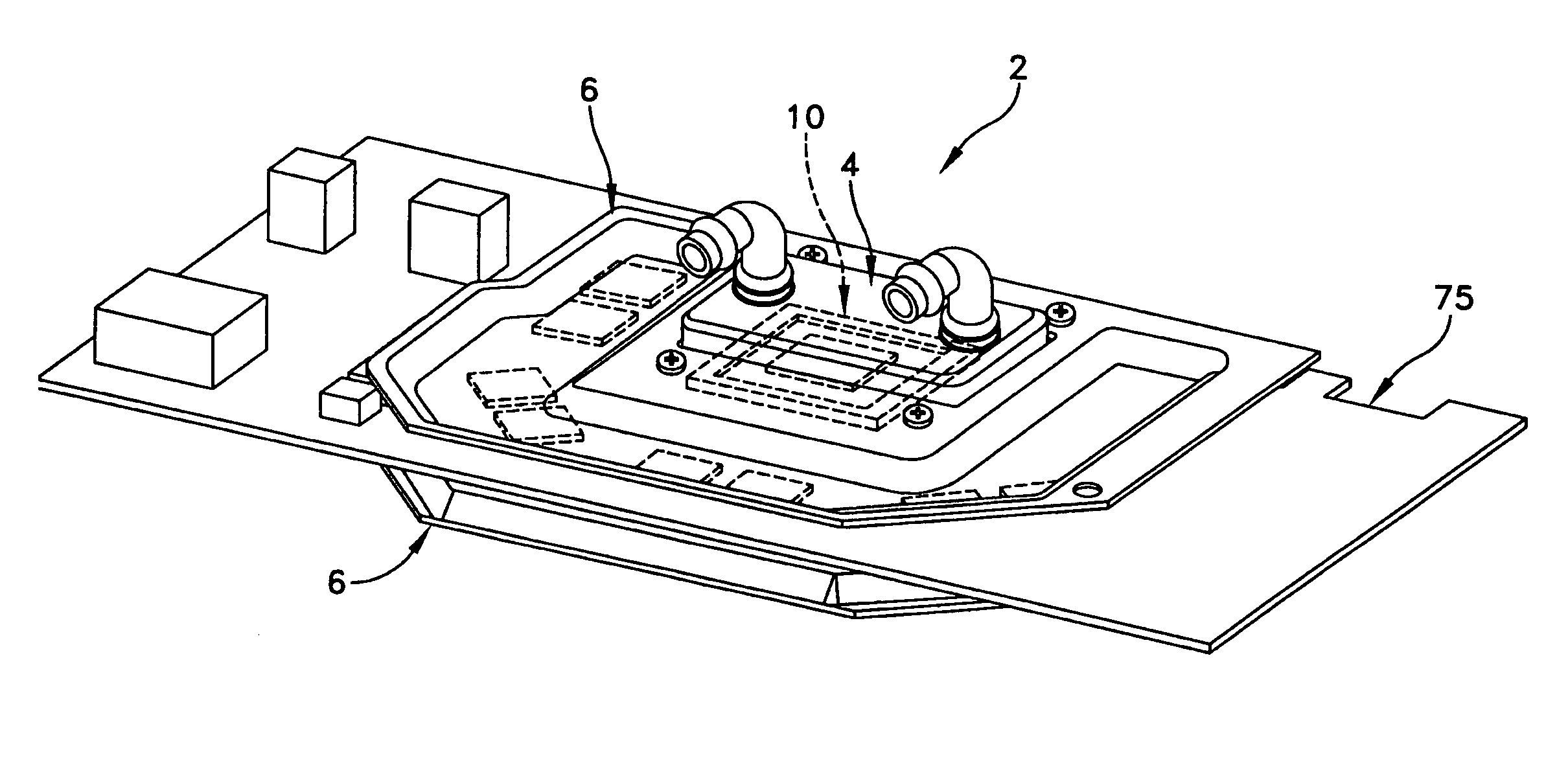
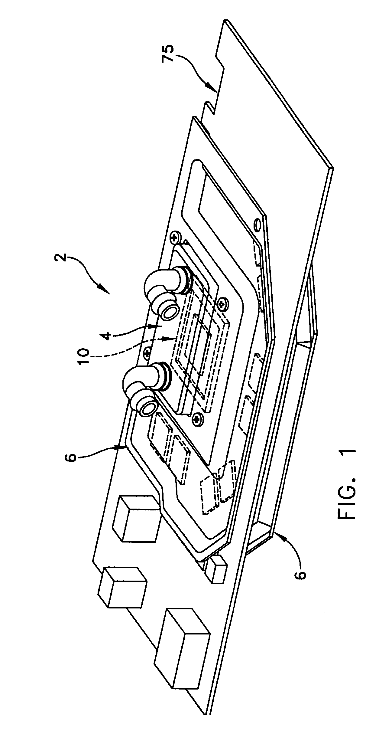
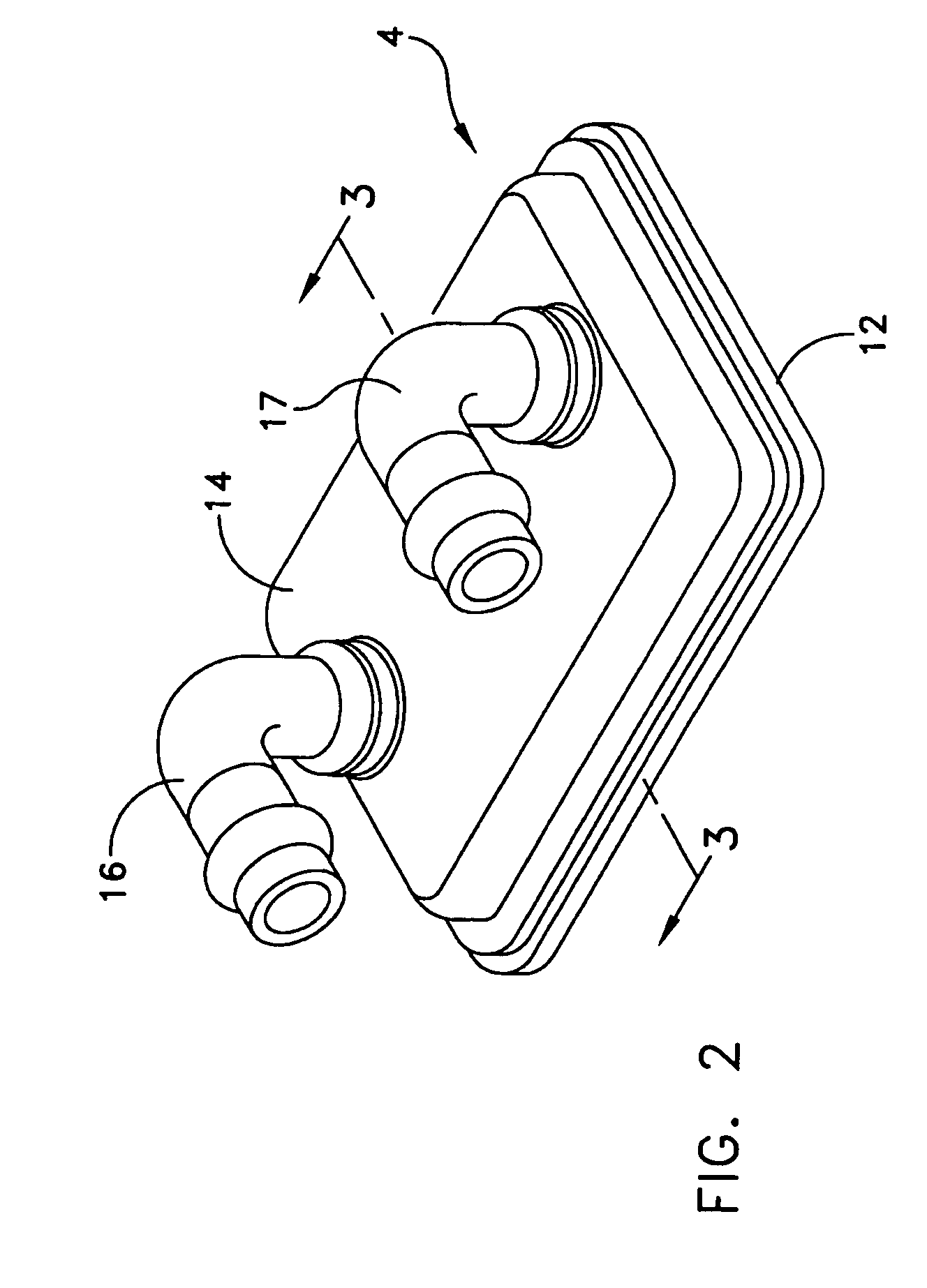
[0023] This description of preferred embodiments is intended to be read in connection with the accompanying drawings, which are to be considered part of 20 the entire written description of this invention. The drawing figures are not necessarily to scale and certain features of the invention may be shown exaggerated in scale or in somewhat schematic form in the interest of clarity and conciseness. In the description, relative terms such as “horizontal,”“vertical,”“up,”“down,”“top” and “bottom” as well as derivatives thereof (e.g., “horizontally,”“downwardly,”“upwardly,” etc.) should be construed to refer to the orientation as then described or as shown in the drawing figure under discussion. These relative terms are for convenience of description and normally are not intended to require a particular orientation. Terms including “inwardly” versus “outwardly,”“longitudinal” versus “lateral” and the like are to be interpreted relative to one another or relative to an axis of elongation...


PUM


Abstract

A system for cooling electronic components with a surface having one or more electronic components, including an integrated circuit, mounted thereon. A liquid cooled heat exchanger located in overlying contacting relation with the integrated circuit. A resilient cold plate coupled to the surface so as to be biased by a portion of the liquid cooled heat exchanger thereby providing a forced engagement between the liquid cooled heat exchanger, the integrated circuit, and the resilient cold plate.

Description

[0001] This nonprovisional patent application claims priority from provisional patent application Ser. No. 60 / 607,933, filed Sep. 8, 2004, entitled Video Graphics Card Memory Modules Liquid Cooled Heat Sink Plus Liquid Cooling Cold Plate Retention Mechanism, which provisional application is incorporated herein by reference in its entirety.FIELD OF THE INVENTION [0002] The present invention generally relates to thermal management for memory modules and, more particularly, to a liquid cooled heat sink and cold plate retention mechanism. BACKGROUND OF THE INVENTION [0003] As the power to be dissipated by semiconductor devices increases with time, a problem arises: over time the thermal conductivity of the available materials becomes too low to conduct the heat from the semiconductor device to the fins with an acceptably low temperature drop. The thermal power density emerging from the semiconductor devices will be so high that even copper or silver spreader plates will not be adequate....

Claims


Application Information

Patent Timeline
Patent Type & Authority Applications(United States)
IPC IPC(8): H05K7/20
CPCH01L23/473H01L2924/0002H01L2924/00
Inventor WILSON, MICHAEL J.WATTELET, JONATHANLIGHTNER, DONALDDEKEUSTER, RICHARDDUBBLE, ERNEST H.BALDASSARRE, GREGG J.
Owner THERMAL
Why Eureka
Try Eureka