

Controlled inrush current limiter
a limiter and inrush current technology, applied in the direction of electric variable regulation, process and machine control, instruments, etc., can solve the problems of reducing the efficiency of the power supply circuit, reducing the charging rate of the capacitor, and discharging power
- Summary
- Abstract
- Description
- Claims
- Application Information
AI Technical Summary
Benefits of technology
Problems solved by technology
Method used
Image

Examples
Embodiment Construction
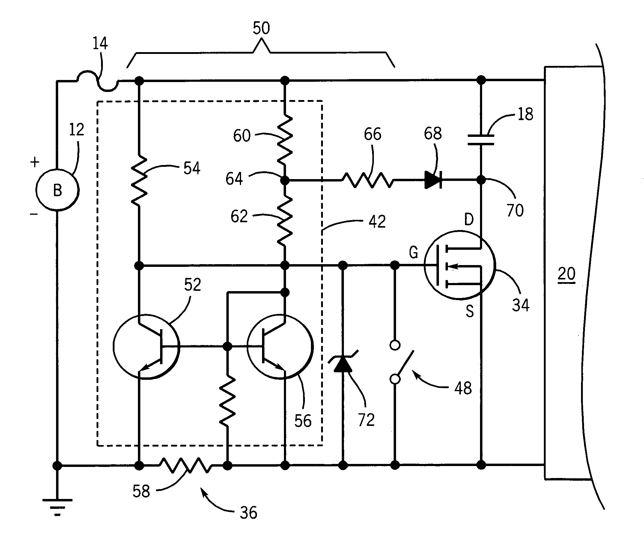
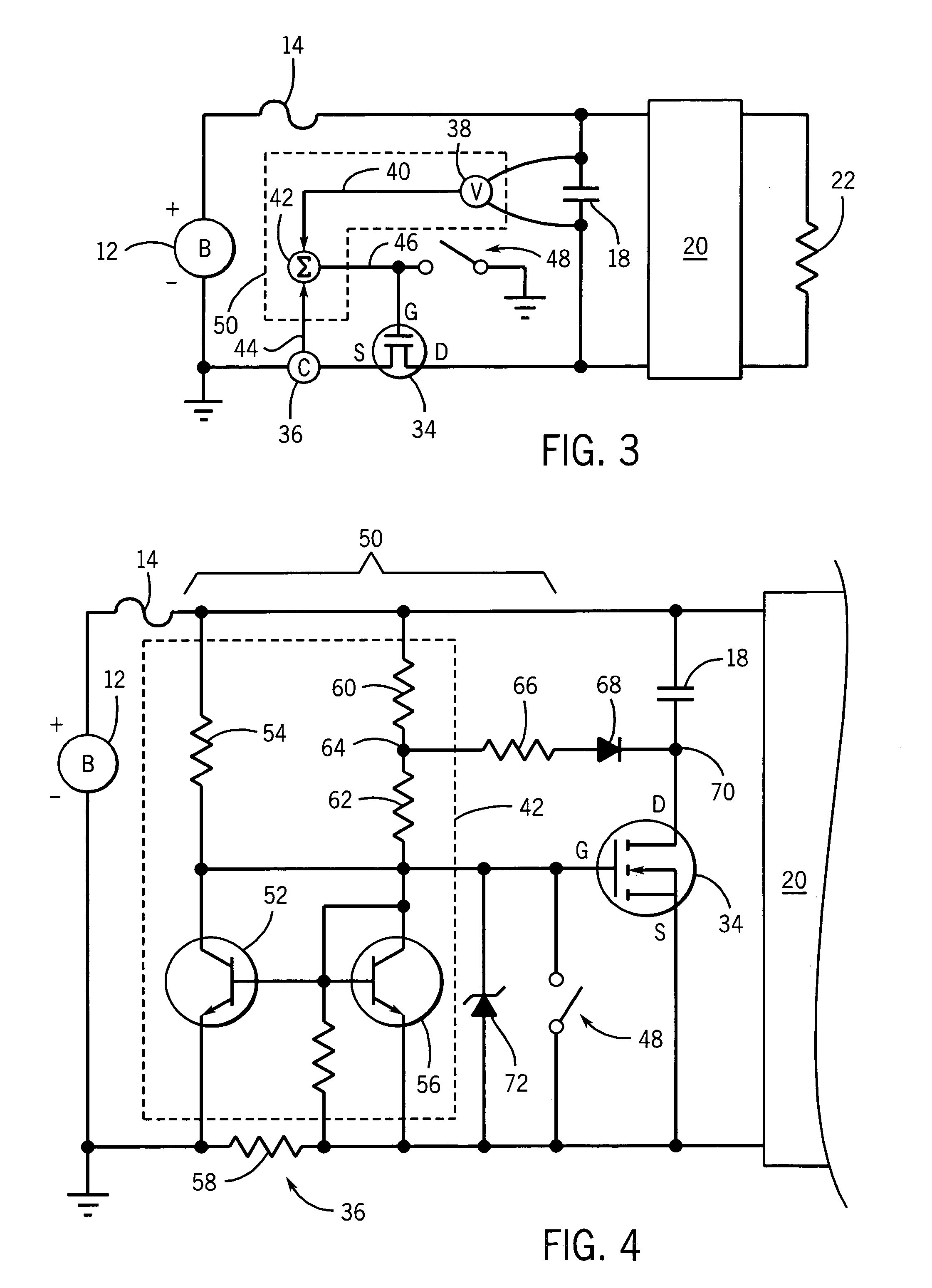
[0035] Referring now to FIG. 3, in the present invention, a power source 12, such as a battery providing twelve or twenty-four volts of electricity, may have a positive terminal connected with a first terminal of a fuse 14 and a second terminal defining a ground point.
[0036] The second terminal of the fuse 14 is connected directly to a first terminal of a filter capacitor 18 shunting, for example, input terminals of a DC-to-DC converter 20 or other load. The second terminal of the filter capacitor 18 may be connected to the drain terminal of a field effect transistor (FET) 34 and the source terminal of this transistor 34 may be connected through a current sensing circuit 36 to ground.
[0037] A voltage sensing circuit 38 may communicate with the capacitor 18 to measure the voltage across the capacitor which, in conjunction with the known capacitance value of the capacitor 18, indicates a state of charge of the capacitor 18.
[0038] The voltage sensing circuit 38 provides a voltage va...
PUM
 Abstract
Description
Claims
Application Information