Electro-acoustic transducer with two diaphragms

a diaphragm and transducer technology, applied in the direction of transducer details, electric transducers, electrical apparatus, etc., can solve the problems of reducing sound quality, reducing design parameters, and reducing sound quality

Inactive Publication Date: 2006-03-09
VAN HALTEREN AART ZEGER +1
View PDF7 Cites 10 Cited by
  • Summary
  • Abstract
  • Description
  • Claims
  • Application Information

AI Technical Summary

Benefits of technology

[0011] It is an object of the present invention to provide an electro-acoustical transducer of very compact dimensions for general use in telecommunication equipment and hearing aid devices.
[0015] 3. high efficiency due to optimised magnetic circuit with low leakage.

Problems solved by technology

Such loops may lead to reduced sound quality.
In case of large gains, such as in hearing aids, the mentioned feedback loops may even lead to disturbing howling sounds, and thus being a limiting factor in the maximum possible gain of the hearing aid.
A disadvantage of the rubber boot construction is that it does not provide enough vibration isolation and it is very difficult to design and control the design parameters.
The box-in-a-box construction easily gets very large and bulky.
However, the speaker system described in JP 11 308691 A has a disadvantage since its magnetic circuit and the diaphragms are circular with the entire coil positioned in the circular magnetic gap.
In addition, the magnetic circuit is bulky and is thus not suited for applications with very limited space available, especially with respect to the height of the speaker system.
Furthermore, the speaker system of JP 11 308691 A requires a large number of single components, and therefore it is not suited for low cost mass production.
The design is bulky by nature, since it relates to the art of superior bidirectional speakers where parameters such as size and weight is not important.
In addition, the above mentioned problem concerning distortion caused by non perfect symmetry in the magnetic circuit is not solved.
Furthermore, due to the large number of single components and complicated geometry the design is not suited for low cost mass production.

Method used


Image

  • Electro-acoustic transducer with two diaphragms
  • Electro-acoustic transducer with two diaphragms
  • Electro-acoustic transducer with two diaphragms

Examples


Embodiment Construction

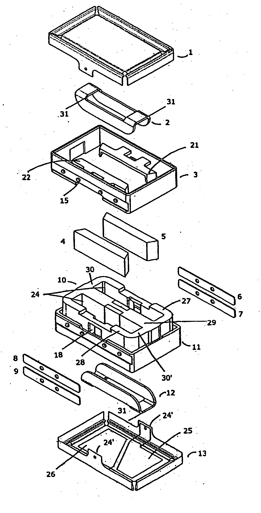
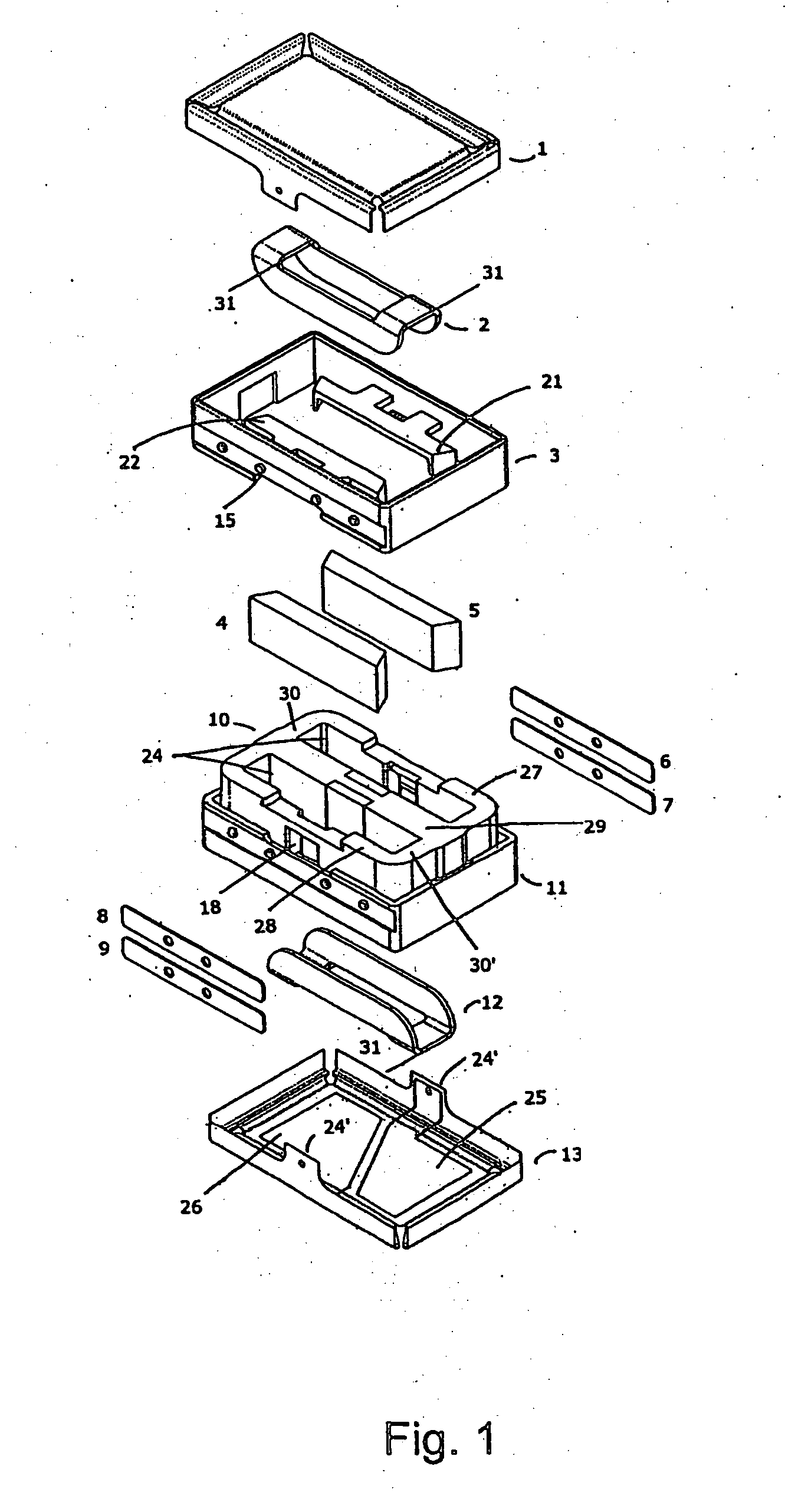
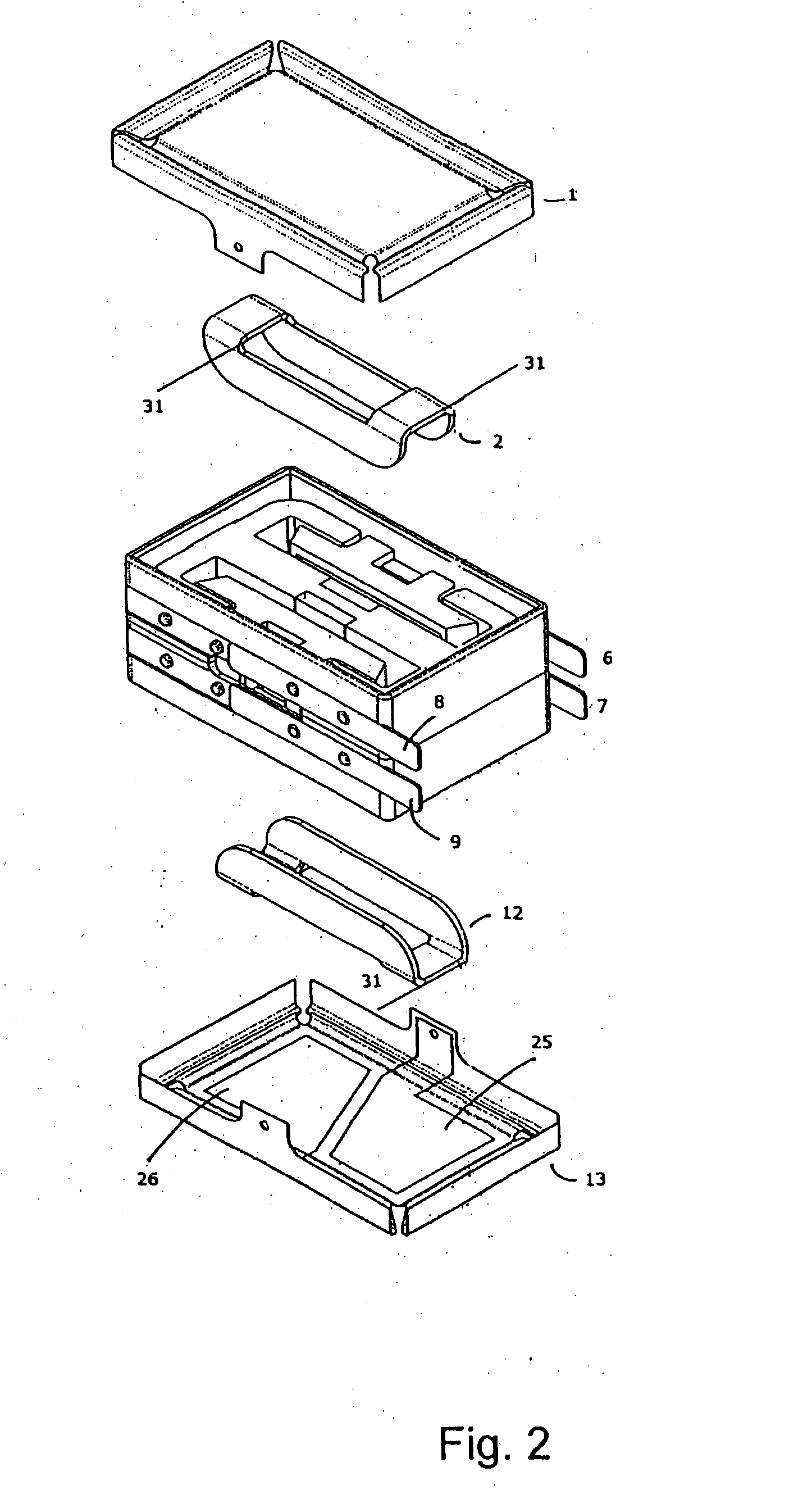
[0050]FIGS. 1-3 show an electro-dynamic transducer with its main components: a magnetic circuit 10, a first coil 2, a second coil 12, a first diaphragm 1, a second diaphragm 13, and four terminals 6-9.

[0051] As is best seen in FIG. 1, the electro-dynamic transducer according to the present invention comprises two diaphragms 1, 13 and two coils 2, 12 which have a common magnetic circuit. The two diaphragms may be driven in two modes of operation—either with the same polarity or in opposite polarity. In case the two diaphragms are driven in the same direction in response to an incoming electric signal, the transducer is driven in a so-called vibration mode. Vibration mode leads to maximum vibration but no sound output. In case the two diaphragms are driven in opposite directions maximum sound output is provided, and the transducer is vibration-free. Terminals 6 and 8 provide electrical contact to coil 2, whereas terminals 7 and 9 provide electrical contact to coil 12. The contact bet...


PUM


Abstract

The present invention relates to an electro-acoustic transducer suitable for applications within mobile communication equipment and hearing aids. The transducer comprises two diaphragms positioned on opposite sides of a magnetic circuit having two magnetic gaps. When used as a microphone the transducer is substantially insensitive to vibrations, and when used as a speaker the transducer generates only very low vibration levels. The magnetic circuit has a number of advantages compared to conventional transducers with circular magnetic. The transducer can be made lightweight and with very compact dimensions compared to conventional designs. In a preferred embodiment the diaphragms are rectangular. The transducer may additionally be used as a vibration generator for silent alarm signals.

Description

FIELD OF THE INVENTION [0001] The present invention relates to electro-acoustic transducers, and in particular to electro-dynamic transducers with two diaphragms each carrying a coil of electrically conducting wire movable in a magnetic field. BACKGROUND OF THE INVENTION [0002] Electro-acoustic transducers, and in particular electro-dynamic transducers, are widely used in e.g. telecommunication equipment such as wired, mobile or cellular telephones, and hearing aids where small size is a requirement. Both transducers used as microphones and loudspeakers (speakers) are used for transforming acoustical signals into electrical signals and vice versa. For both microphones and speakers to be used in miniature equipment it is essential that the transducer is tolerant with respect to vibrations in order to avoid unintended noise or feedback problems. [0003] With a microphone and speaker placed close to each other, such as especially in hearing aids, a feedback loop may occur due to vibrati...

Claims


Application Information

Patent Timeline
Patent Type & Authority Applications(United States)
IPC IPC(8): H04R25/00H04R9/06
CPCH04R9/025H04R9/046H04R31/006H04R25/00H04R9/063H04R9/06
Inventor VAN HALTEREN, AART ZEGERJOHANNSEN, LEIF
Owner VAN HALTEREN AART ZEGER
Why Eureka
Try Eureka