Integrated co-injection molded vehicle components and methods of making the same
What is AI technical title?
AI technical title is built by Patsnap AI team. It summarizes the technical point description of the patent document.
a co-injection molding and vehicle technology, applied in the field of vehicle components, can solve the problems of considerable effort and cost, known bumpers and methods for manufacturing them are characterized by relatively high production costs, and achieve the effects of reducing the density of the core, reducing the weight of the component, and reducing the cos
Inactive Publication Date: 2006-03-09
CONIX
View PDF2 Cites 15 Cited by
Summary
Abstract
Description
Claims
Application Information
AI Technical Summary
This helps you quickly interpret patents by identifying the three key elements:
Problems solved by technology
Method used
Benefits of technology
Benefits of technology
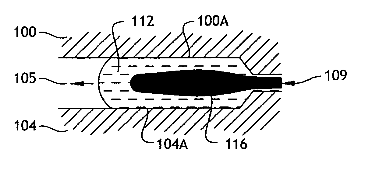
The present invention provides a method for integrating flexible and rigid components in vehicle components using a co-injection molding process. This allows for the fabrication of components that have both flexible and rigid portions, such as bumpers, fenders, door panels, and trunk lids. The method uses a single mold to integrate the flexible and rigid components, resulting in a seamless appearance on the exposed surface of the components. The invention also provides a way to mold multiple bumper pieces into a single unitary piece or section, adding strength and flexibility to the bumper without visible sink areas on the exposed surface. The invention also includes a process for forming a fluid channel in the molded article, which results in increased structural integrity and can be used for reinforcing members in vehicles.
Problems solved by technology
In the prior art, the flexible bumper components are typically molded separately and then assembled manually or robotically to the rigid components with the expenditure of considerable effort and cost.
Thus, known bumpers and methods for manufacturing them are characterized by relatively high production costs because of the effort required to assemble the flexible and rigid components together.
Method used
Image
Click on the blue label to locate the original text in one second.
Reading with bidirectional positioning of images and text.
Examples
Embodiment Construction
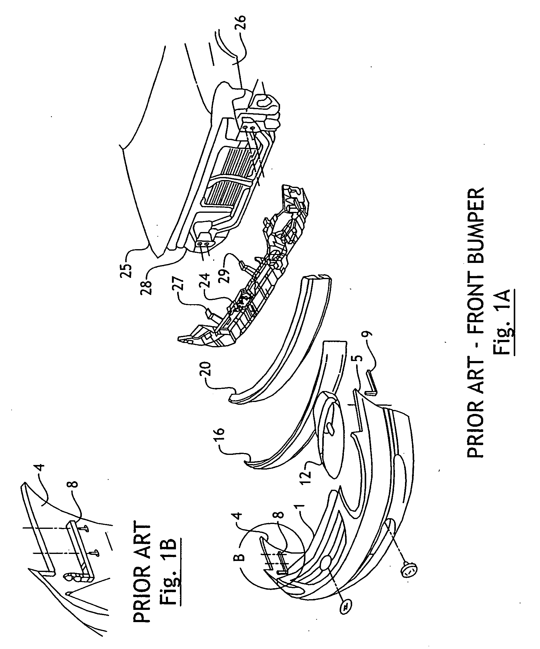
[0047]FIG. 1A depicts an exploded view of a prior art front vehicle bumper. The bumper has flexible components and rigid components. The flexible components include the fascia 1 which covers the other components in an aesthetically pleasing manner. The rigid components include the radiator opening support 24, which attaches to the primary body structure 28, fender attachment brackets 8 and 9, which attach the fascia 1 to the radiator opening support 24 and head lamp housing 12. An energy absorption structure is formed by a rigid bumper beam 20 and foam cap 16 which are disposed between the fascia 1 and the primary body structure 28.
[0048] During assembly, the radiator opening support 24 is attached to the primary body structure 28. The bumper beam 20 is attached to body structure 28, foam cap covering 16 is attached to bumper beam 20, and the headlight lamp holder 12 is then attached to the radiator opening support 24. Finally, the flexible fascia 1 is attached to the radiator open...
PUM
Property
Measurement
Unit
flexible
aaaaa
aaaaa
shape
aaaaa
aaaaa
Density
aaaaa
aaaaa
Abstract
A vehicle bumper (20) integrates rigid and flexible components into a single co-injection molded structure. In a preferred embodiment, a flexible fascia (58) is provided with integrated rigid fastener brackets (62, 66, 70, 71), energy absorption structure and head lamp brackets and housings (62). A method for manufacturing such a bumper provides for the injection of two different plastic materials during the same molding process. The flexible plastic material first injected into the mold. Then, the rigid plastic material is injected at gates located where the rigid material is desired. In one embodiment, the rigid material is completely contained within the flexible material. The rigid material may be either a higher stiffness plastic or a fiber reinforced plastic.
Description
[0001] This is a divisional application that claims priority to U.S. Ser. No. 10 / 204,734, filed Dec. 10, 2002, which is a 371 of PCT / US01 / 05849, filed Feb. 23, 2001 which, claims priority to provisional application Ser. Nos. 60 / 184, 743, entitled “Injection Molding Techniques Utilizing Fluid Channels,” 60 / 184,639, entitled “Integrated Co-Injection Molded Bumpers and Methods of Making the Same,” and 60 / 184,564, entitled “Low-Density Injection-Molded Body Parts,” which were all filed on Feb. 24, 2000, and Ser. No. 60 / 264,916, entitled “Multi-Part Sequential Valve Gating,” which was filed Jan. 29, 2001, all of which are incorporated herein by reference.FIELD OF THE INVENTION [0002] The present invention relates generally to vehicle components, such as vehicle bumpers, and methods for manufacturing the same. More particularly, the invention relates to co-injection molded vehicle components, such as vehicle bumpers, which have integrated flexible and rigid structures. The invention also ...
Claims
Application Information
Patent Timeline
Application Date:The date an application was filed.
Publication Date:The date a patent or application was officially published.
First Publication Date:The earliest publication date of a patent with the same application number.
Issue Date:Publication date of the patent grant document.
PCT Entry Date:The Entry date of PCT National Phase.
Estimated Expiry Date:The statutory expiry date of a patent right according to the Patent Law, and it is the longest term of protection that the patent right can achieve without the termination of the patent right due to other reasons(Term extension factor has been taken into account ).
Invalid Date:Actual expiry date is based on effective date or publication date of legal transaction data of invalid patent.
Patent Type & AuthorityApplications(United States)

