Variable valve system of internal combustion engine and control method thereof
- Summary
- Abstract
- Description
- Claims
- Application Information
AI Technical Summary
Benefits of technology
Problems solved by technology
Method used
Image
Examples
first embodiment
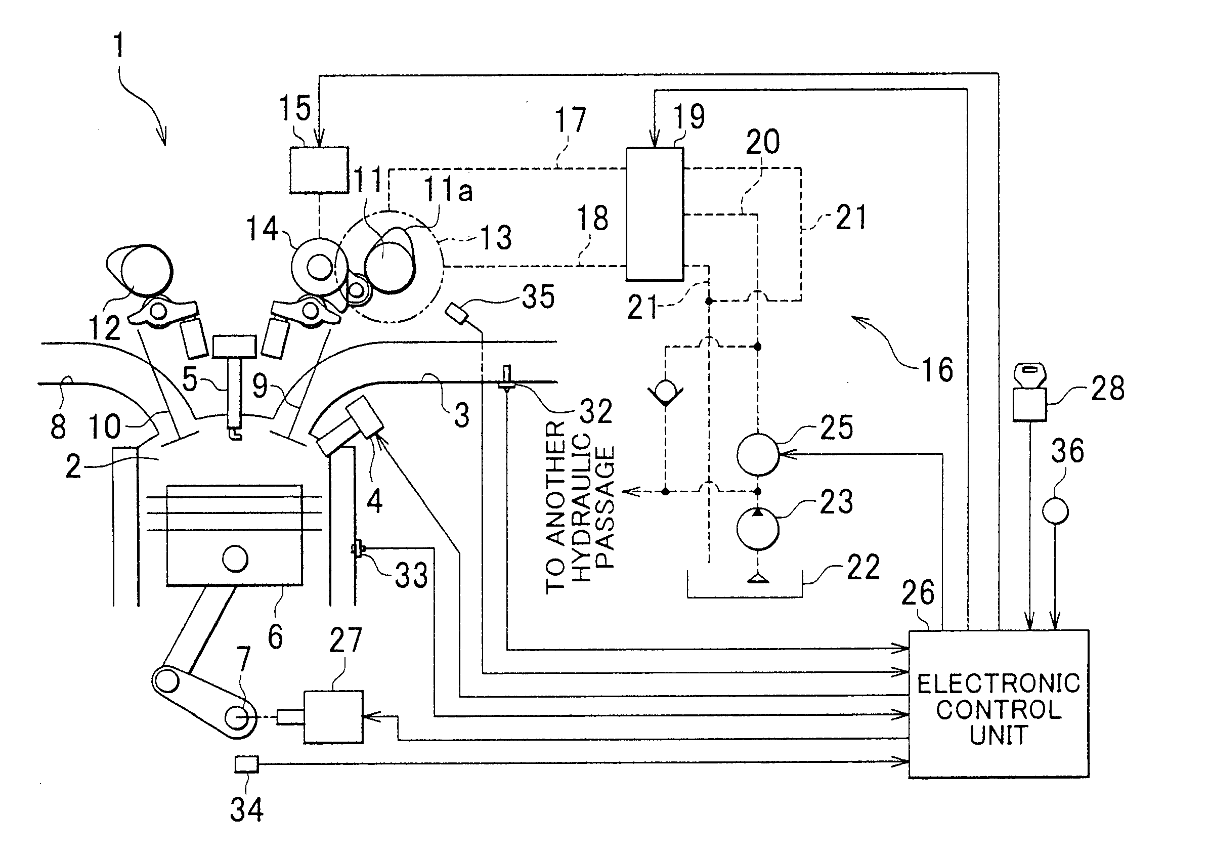
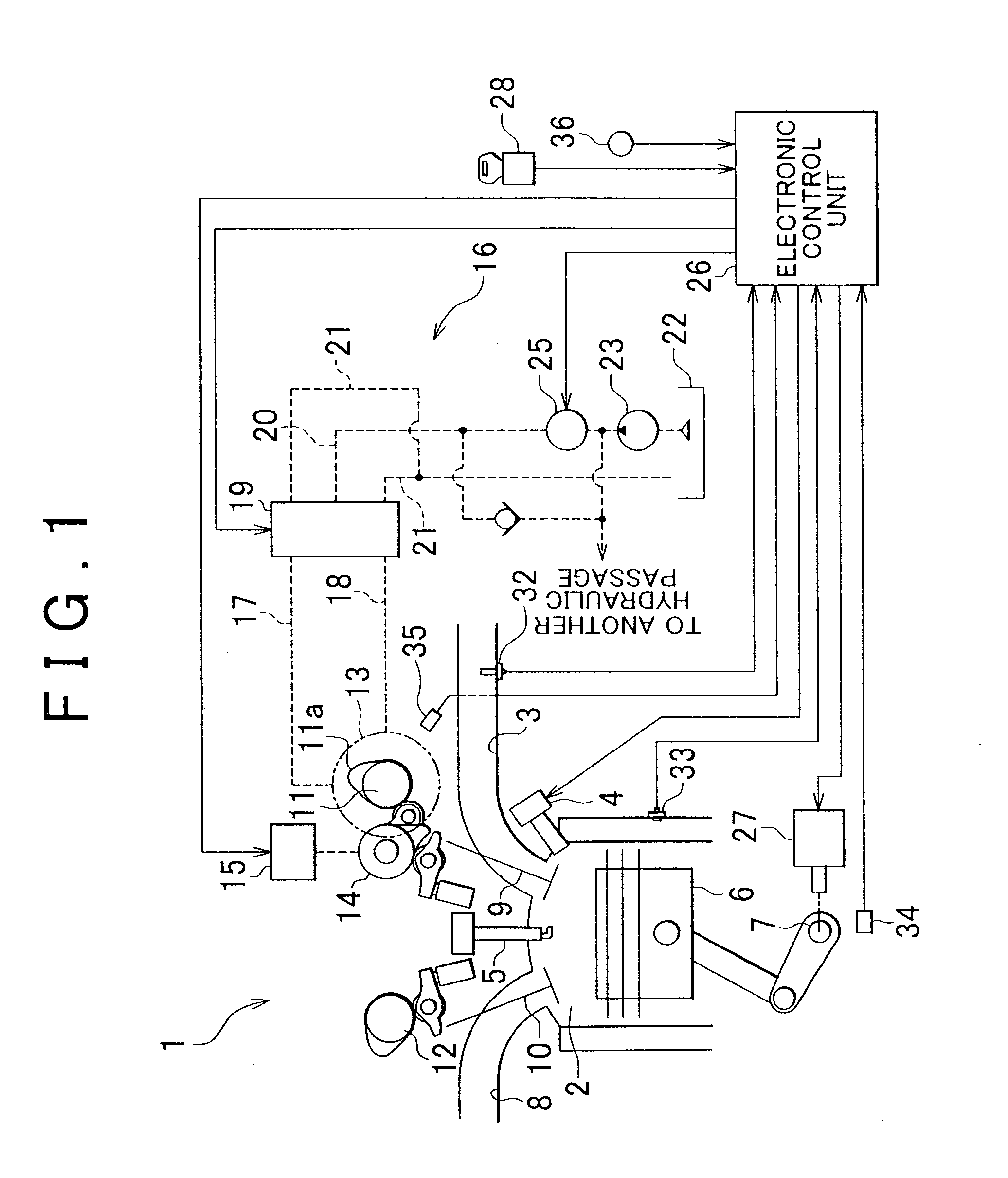
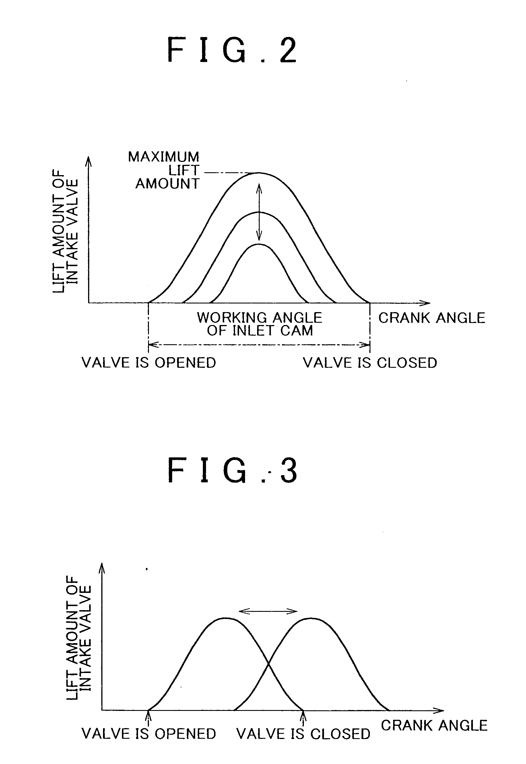
[0046] Hereafter, a first embodiment of the invention will be described with reference to FIGS. 1 to 10. The first embodiment relates to a variable valve system of an in-cylinder injection spark ignition type engine mounted in an automobile.
[0047] In an engine 1 shown in FIG. 1, air is supplied to a combustion chamber 2 through an intake passage 3, and fuel is directly injected from a fuel injection valve 4. When a spark plug 5 ignites an air-fuel mixture formed of the thus supplied air and fuel, the air-fuel mixture is burned and a piston 6 reciprocates, causing a crankshaft 7 serving as an output shaft of the engine 1 to rotate. The burned air-fuel mixture, that is, exhaust gas, is discharged from the combustion chamber 2 to an exhaust passage 8. A starter 27, which forcibly rotates the crankshaft 7 that has been stopped when the engine 1 is started, is connected to the crankshaft 7.
[0048] In the engine 1, communication between the combustion chamber 2 and the intake passage 3 i...
second embodiment
[0096] Hereafter, a second embodiment of the invention will be described with reference to FIGS. 11 and 12. In the second embodiment, the work rate of the electric oil pump 25 is changed based on the amount of difference between the actual valve timing and the target valve timing, unlike the first embodiment in which the work rate of the electric oil pump 25 is changed based on the temperature of the oil supplied to the valve timing changing mechanism 13.
[0097]FIG. 11 is a flowchart showing a drive duty ratio calculating routine in the second embodiment. In the drive duty ratio calculating routine, first, the amount of difference between the actual valve timing and the target valve timing is calculated in step S301. When the actual valve timing is adjusted to the target valve timing by performing the valve timing control, as the oil temperature increases and the response of the valve timing changing mechanism 13 is delayed, the adjustment-speed characteristic that adjusts the actua...
third embodiment
[0101] Hereafter, a third embodiment of the invention will be described with reference to FIGS. 13 and 14. In the third embodiment, the work rate of the electric oil pump 25 is changed based on the duty ratio command value used for controlling driving of the OCV 19, instead of changing the work rate of the electric oil pump 25 in the manner mentioned in the first embodiment and the second embodiment. More specifically, the work rate of the electric oil pump 25 is changed based on which region in the range “from −50% to 50%” the duty ratio command value is in, namely, based on the driving region of the valve timing changing mechanism 13.
[0102]FIG. 13 is a flowchart showing a drive duty ratio calculating routine in the third embodiment. In the drive duty ratio calculating routine, first, it is determined in step S401 which of the regions “from Ai to Ai+n” and “from −Ai to −Ai to+n” in the range “from −50% to 50%” shown in FIG. 14 the duty ratio command value is in.
[0103] The region ...
PUM
 Abstract
Description
Claims
Application Information
 - R&D
- Intellectual Property
- Life Sciences
- Materials
- Tech Scout
- Unparalleled Data Quality
- Higher Quality Content
- 60% Fewer Hallucinations
Browse by: Latest US Patents, China's latest patents, Technical Efficacy Thesaurus, Application Domain, Technology Topic, Popular Technical Reports.
© 2025 PatSnap. All rights reserved.Legal|Privacy policy|Modern Slavery Act Transparency Statement|Sitemap|About US| Contact US: help@patsnap.com


