Fast codec with high compression ratio and minimum required resources

a codec and compression ratio technology, applied in the field of data compression and decompression methods and apparatuses, can solve the problems of blocking artifacts at high compression ratios, direct coding using entropy coders that cannot achieve satisfactory compression ratios, and human visual systems are very sensitive to such type of image distortion. , to achieve the effect of fast adaptation

Active Publication Date: 2006-03-09
CEPERKOVIC VLADIMIR +3
View PDF9 Cites 45 Cited by
  • Summary
  • Abstract
  • Description
  • Claims
  • Application Information

AI Technical Summary

Benefits of technology

[0031] The third object of this invention is to provide novel simple context modeling and symbol probability estimation using a minimum number of histograms with fast adaptation for the sign and the magnitude of the transformation coefficients, provided by the second object of this invention, in order to fulfill the first object of this invention.

Problems solved by technology

For most types of images, direct coding using an entropy coder does not achieve satisfactory compression ratio, so some form of prior decomposition is necessary.
The main drawbacks of block transformation methods, like discrete cosine transform (DCT), are blocking artifacts at high compression ratios, which are especially visible in image regions with low local variance.
Unfortunately, human visual system is very sensitive to such type of image distortion.
However, such filters are relatively long and thus unsuitable for image-coding applications.
These algorithms are usually limited to prior statistical model with fixed parameters, which typically leads to lower compression ratio than achieved by other methods.
All these methods store the complete image in the memory and require relatively large number of passes to encode / decode image.
Unfortunately, two-pass algorithm is necessary for the calculation of density function parameters.
Furthermore, experimental results show significant disagreement between this density function and actual histograms at higher levels of subband transformation.
However, tiling produces blocking artifacts at the boundaries between blocks.
Another serious drawback is quality degradation at higher compression ratios and limited maximum acceptable compression ratio.

Method used


Image

  • Fast codec with high compression ratio and minimum required resources
  • Fast codec with high compression ratio and minimum required resources
  • Fast codec with high compression ratio and minimum required resources

Examples


first embodiment

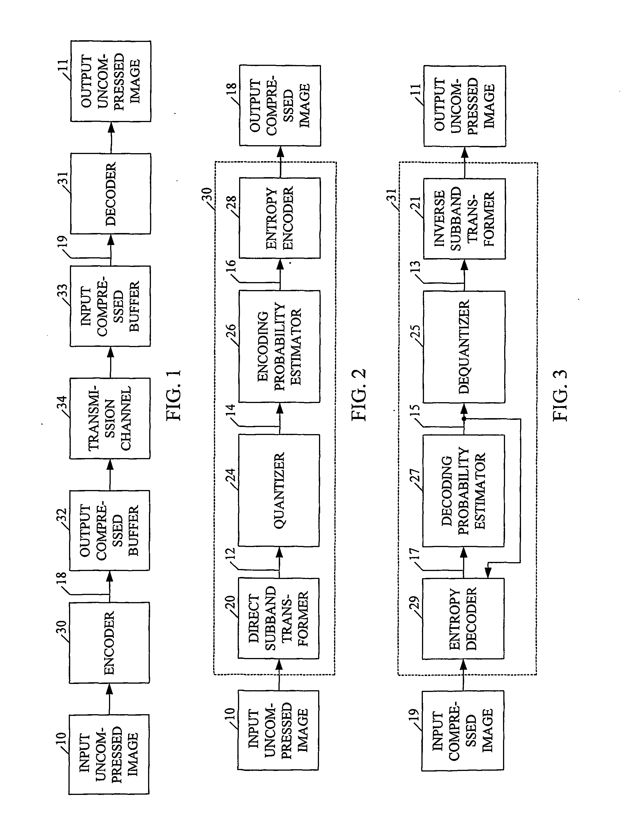
[0096]FIG. 9 and FIG. 10 are block diagrams of the encoder 30 and the decoder 31 of this invention, with N=3 levels of D1DST and I1DST, respectively.

TABLE 62DSTTotal synchronization memory size per subband [coefficient]levelSynchronization memory size for 3 subbands (LH, HL and HH) is 3 times higher0(D+2·D+22·D+…+2N-2·D)·W2=W2·∑k=0N-2⁢2k·D=(2N-1-1)·D·W21(D+2·D+22·D+…+2N-3·D)·W4=W4·∑k=0N-3⁢2k·D=(2N-2-1)·D·W42(D+2·D+22·D+…+2N-4·D)·W8=W8·∑k=0N-4⁢2k·D=(2N-3-1)·D·W8n(D+2·D+22·D+…+2N-m-2·D)·W2n+1=W2n+1·∑k=0N-n-2⁢2k·D=(2N-n-1-1)·D·W2n+1N-3(D+2·D)·W2N-2=3·D·W2N-2N-2D·W2N-1All levels∑n=0N-2⁢(2N-n-1-1)·D·W2n+1=13·(2N-3+12N-1)·D·WAll levels and all subbands3·∑n=0N-2⁢(2N-n-1-1)·D·W2n+1=(2N-3+12N-1)·D·W

[0097] Instead of buffering the transformation coefficients in the synchronization memory of the encoder 30, input uncompressed data are direct subband transformed in D1DSTs 100-102, using direct non-stationary filters, transformation coefficients are quantized in quantizers 140-143, the probabili...

second embodiment

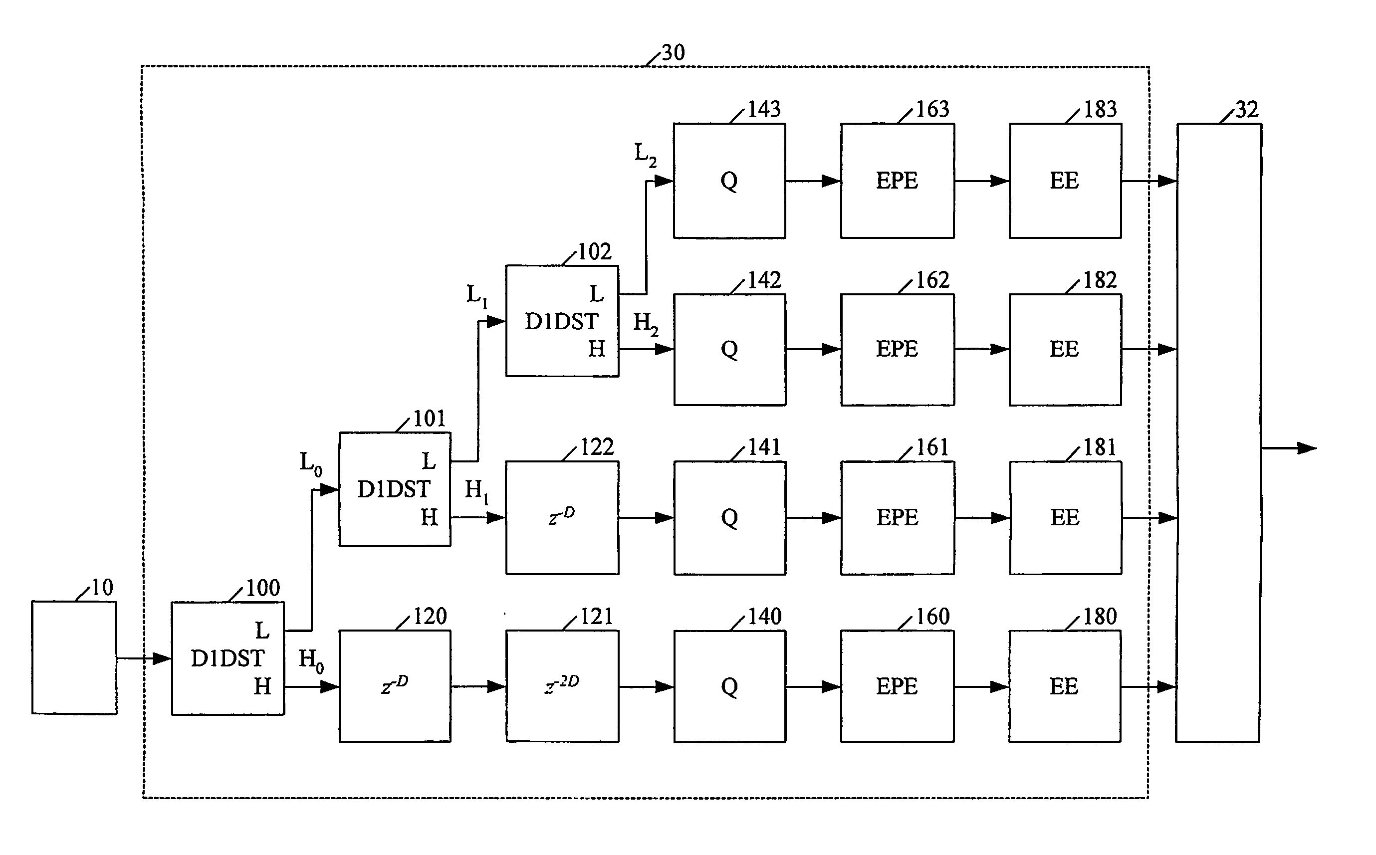
[0103]FIG. 13 and FIG. 14 are block diagrams of the encoder 30 and the decoder 31 of this invention, with N=3 levels of D1DST and I1DST, respectively.

[0104] Instead of buffering the compressed transformation coefficients in the synchronization memory of the encoder 30, input uncompressed data is direct subband transformed in D1DSTs 100-102, using direct non-stationary filters, transformation coefficients are quantized in quantizers 140-143, the probabilities of transformation coefficients within the specified contexts are estimated in the encoding probability estimators 160-163, the quantized transformation coefficients are entropy encoded in the entropy encoders 180-183 and finally in theirs compressed form stored into the output compressed buffer 32, which temporarily serves as the synchronization memory, from which they will be transmitted.

[0105] Instead of buffering the compressed transformation coefficients in the synchronization memory of the decoder 31, input compressed data...

third embodiment

[0127]FIG. 27 is a block diagram of the direct non-stationary filter of this invention, made of sequentially connected four first-order direct NSFCs: F4=F−1,−1,[α],[α] (x, c) 1020, F5=F−1,−1,[β],[β](x,c) 1021, F6=F1,1,[γ],[γ](x,c) 1022 and F7=F1,1,[Δ],[Δ](x,c) 1023, with parameters given in the TABLE 8.

[0128]FIG. 28 is a block diagram of the third embodiment of the inverse non-stationary filter of this invention, made of sequentially connected four first-order direct NSFCs: F7−1=F−1,−1,[Δ],[Δ](x,c) 1033, F6−1=F−1,−1,[γ],[γ](x,c) 1032, F5−1=F1,1,[β],[β](x,c) 1031 and F4−1=F1,1,[α],[α](x,c) 1030, with parameters given in the TABLE 8.

TABLE 8ParameterValueα1.58193248659365β0.07167834102835γ0.82577375069311Δ0.52307224508739G10.76323962993937G21.31020450298084

[0129] It should be also noticed that all filter embodiments use a symmetrical extension of input data at the image boundaries. However, it is possible to implement non-stationary filter coefficients near image boundaries, in order...


PUM


Abstract

This invention provides a novel single-pass and multi-pass synchronized encoder and decoder, performing order(s) of magnitude faster data compression and decompression, at any compression ratio with the higher or the same perceived and measured decompressed image quality in comparison with the best state-of-the-art compression methods, using order(s) of magnitude less system resources (processor complexity, memory size, consumed power, bus bandwith, data latency). These features are achieved using novel direct and inverse non-stationary filters for the recusive octave direct and inverse subband transformation, novel simple context modeling and symbol probability estimation using a minimum number of histograms with the fast adaptation for the sign and the magnitude of the transformation coefficients, a novel accelerated range coder without division operations, and a novel synchronisation of the compressed data.

Description

TECHNICAL FIELD [0001] This invention generally relates to the methods and apparatus for data compression and decompression, and more particularly still and moving image lossless and lossy compression and decompression. [0002] State-of-the-art data compression methods with high compression ratio are time consuming and require complex processors and large memory with high bus bandwidth, which increase consumed power. [0003] The presented technical problem is solved by this invention, which provides order(s) of magnitude faster data compression and decompression, at any compression ratio with the higher or the same perceived and measured decompressed image quality in comparison with the best state-of-the-art compression methods, using order(s) of magnitude less system resources, due to the application of novel direct and inverse non-stationary filters, novel simple context modeling and symbol probability estimation using a minimum number of histograms with the fast adaptation, a novel...

Claims


Application Information

Patent Timeline
Patent Type & Authority Applications(United States)
IPC IPC(8): G10L21/00H03M7/40H04N1/41H04N7/30H04N7/24H04N7/26
CPCH04N19/13H04N19/63H04N19/115H04N19/61H04N19/146H04N19/1883H04N19/635H04N19/42
Inventor CEPERKOVIC, VLADIMIRPAVLOVIC, SASAMIRKOVIC, DUSAN
Owner CEPERKOVIC VLADIMIR
Why Eureka
Try Eureka