
PECVD susceptor support construction

Inactive Publication Date: 2006-03-16
APPLIED MATERIALS INC
View PDF33 Cites 26 Cited by
  • Summary
  • Abstract
  • Description
  • Claims
  • Application Information

AI Technical Summary

Benefits of technology

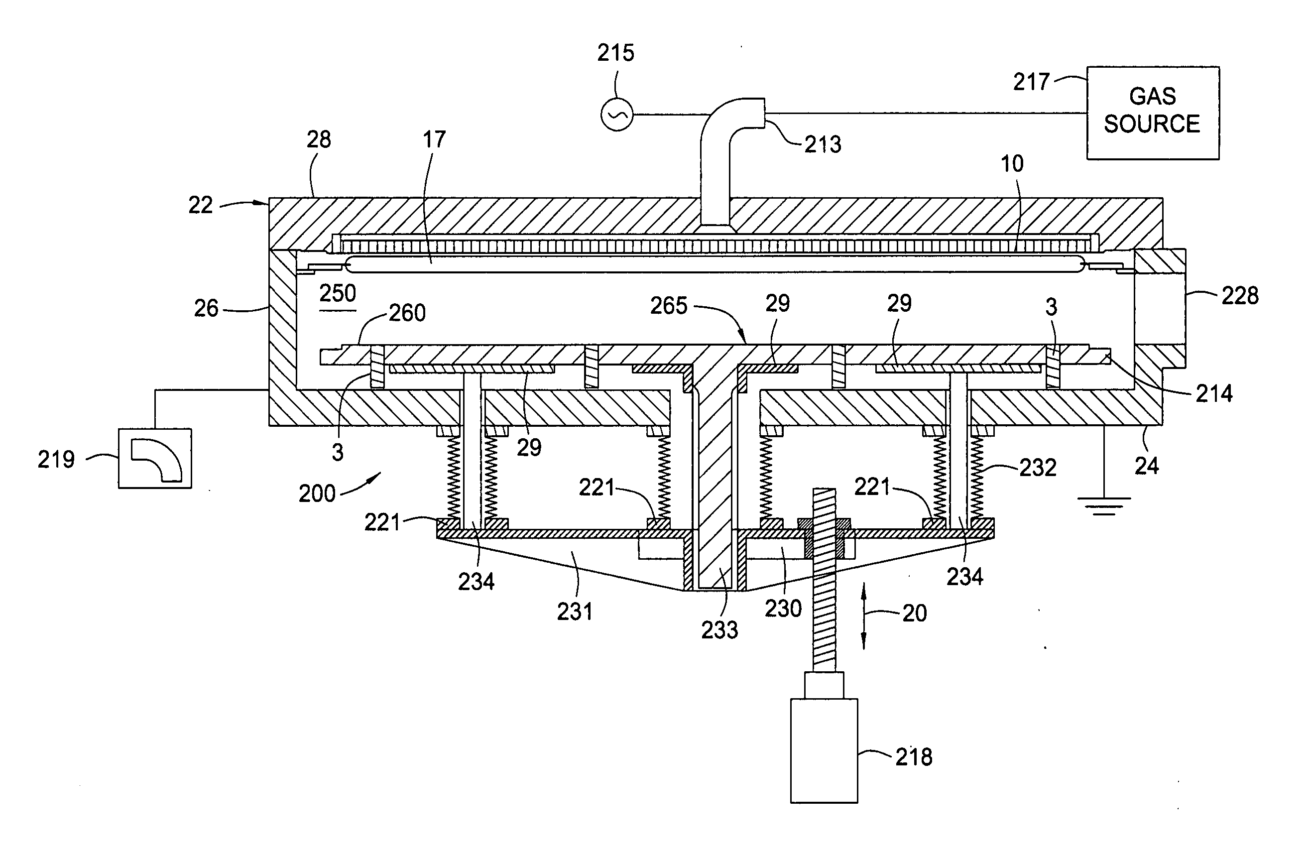
[0013] The present invention generally provides a solution to the problems encountered by using large ceramic monoliths to support a large area susceptor by replacing the currently used support assembly with a plurality of smaller support plates positioned to maintain a desired cross-sectional horizontal profile and reduce warping of the susceptor, which translates to a conforming large area substrate.

Problems solved by technology

The processes employed are time intensive and profitable production relies on high throughput resulting in usable and operable flat panel displays.
Therefore, producers cannot afford to produce one inoperable unit, much less, a plurality of unusable units caused by non-uniform deposition.
The CVD and PECVD processes that are performed on these substrates generate large amounts of heat.
This increase in size in the ceramic material used to support the susceptor is increasingly expensive.

Method used


Image

  • PECVD susceptor support construction
  • PECVD susceptor support construction
  • PECVD susceptor support construction

Examples


Embodiment Construction

[0031] The present invention generally provides an apparatus and method of supporting a large substrate that minimizes bowing or deflection caused by thermal and gravitational forces and provides a substantially planar surface where a susceptor or substrate support may be supported which, in turn, may support a substrate in a planar or level orientation. Some aspects also provide for isolated lifting points for counteracting substrate support deformation or end sag, or manipulating the susceptor via these lifting points to produce a desired horizontal profile in the susceptor. References made to the horizontal profile and / or the horizontal orientation of various elements depicted in the Figures refers to horizontal cross-sectional views of the particular elements as shown in the Figures.

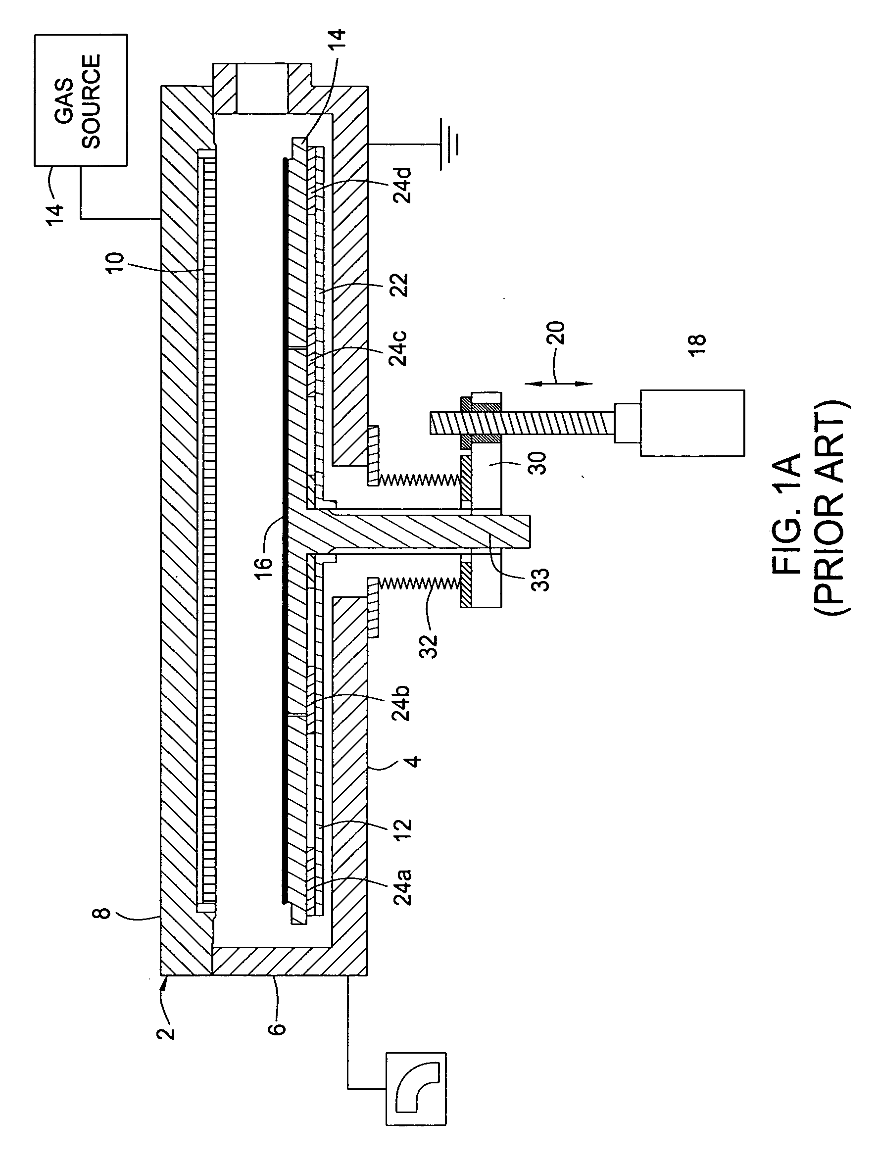
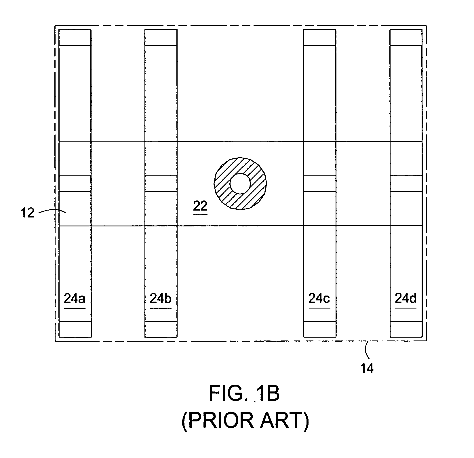
[0032] Embodiments described herein are configured to replace the susceptor support plate assembly 12 shown in FIGS. 1A, 1B by employing a susceptor support assembly having smaller ceramic support p...


PUM

PropertyMeasurementUnit
Shapeaaaaaaaaaa
Areaaaaaaaaaaa
Perimeteraaaaaaaaaa

Abstract

An apparatus and method for maintaining or adjusting the orientation of a large area substrate is disclosed by using multiple support plates disposed below a susceptor adapted to support the large area substrate. The multiple support plates are supported by a plurality of support shafts that are coupled to at least one actuator. The apparatus is designed to selectively adjust the horizontal cross-sectional profile of the susceptor to promote even and uniform processing. The horizontal profile may be one of planar, concave, or convex. The apparatus allows any adjustment to be made before, during, or after processing.

Description

CROSS REFERENCE TO RELATED APPLICATIONS: [0001] This application claims benefit of U.S. Provisional Patent Application No. 60 / 610,634, filed Sep. 15, 2004 (APPM / 009635L), which is incorporated herein by reference to the extent it is not inconsistent with this application.BACKGROUND OF THE INVENTION [0002] 1. Field of the Invention [0003] Embodiments of the present invention generally relate to a substrate processing system in the electronics industry. More specifically, the invention relates to a system and method for supporting large area substrates in flat panel display manufacture. [0004] 2. Description of the Related Art [0005] Flat panel displays typically employ an active matrix of electronic devices, such as insulators, conductors, and thin film transistors (TFT's) to produce flat panel screens used in a variety of devices such as television monitors and computer screens. Generally, these flat panel displays are manufactured on large area substrates which may comprise two thi...

Claims


Application Information

Patent Timeline
IPC IPC(8): C23C16/00
CPCC23C16/4586H01L21/68792H01L21/68778H01L21/68742H01L21/68
Inventor KURITA, SHINICHIKELLER, ERNSTWHITE, JOHN M.
Owner APPLIED MATERIALS INC
Learn More