Solar tracker

a solar tracker and tracker technology, applied in the direction of photovoltaic panels, solar heat collector mounting/support, moving/orienting solar heat collectors, etc., can solve the problems of reducing the yield of panels, limiting the weight and dimensions of asymmetric static loads, and reducing the cooling effect of panels

Active Publication Date: 2006-03-16
ROMEO MANUEL LAHUERTA
View PDF1 Cites 75 Cited by
  • Summary
  • Abstract
  • Description
  • Claims
  • Application Information

AI Technical Summary

Benefits of technology

[0002] More specifically, the invention consists of a solar tracker the structure of which, incorporating an easily accessible individual fixing system, the photovoltaic panels being aligned in rows on different levels on two slopes, with no contact between them, favouring ventilation and allowing them to freely expand and minimizing their structural resistance to wind, allows reaching large dimensions housing a larger number of photovoltaic panels.

Problems solved by technology

This solution hinders panel cooling, reducing their yield due to the temperature increase at a ratio of 0.5% per ° C. This clustering is further limited due to panel expansion since the support structures are rigid and occasionally surrounded by a frame enclosing them, generating stresses between panels due to nighttime and daytime temperature differences.
Another significant drawback is that resulting from their stability given that since they are planar surfaces, the anchor and rotation points are located outside the plane passing through their center of gravity, causing asymmetrical static loads limiting their weight and dimensions so as to not overload the rotation points.
This situation is worsened by the stresses resulting from the wind which generate thrusts and overturning moments making them rather unstable.
On the other hand, when carrying out what is known as “solar farms” by means of tracker clustering, it is necessary to use a large number of trackers, which requires occupying more terrain due to shadows, among other factors, which increases final costs in bases, trenches and electrical infrastructures.
The azimuth tracking axis can furthermore be easily carried out since it is exclusively a time function and therefore uniform throughout the year; the second axis, the tilt axis, varies according to the ellipse of the sun, and its tracking is more complex and occasionally, due to its little gain, it is not worth carrying it out since it complicates the tracker mechanism and reduces its strength.
Another aspect to be taken into account is the lack of foresight with respect to future expansions since most investors in this field at first have doubts or limited resources and begin with smaller installations which in a short time are to be expanded.
This expansion is complicated and expensive if it has not been foreseen from the beginning.

Method used


Image

  • Solar tracker
  • Solar tracker
  • Solar tracker

Examples


Embodiment Construction

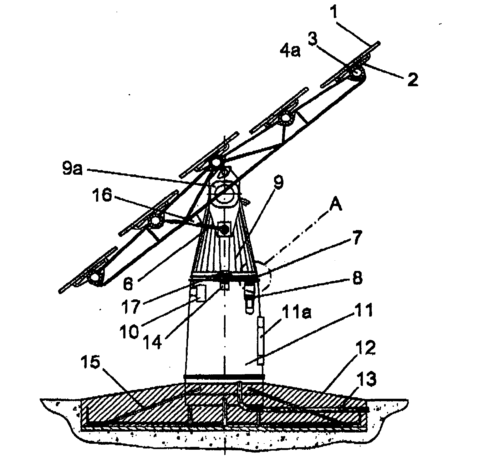
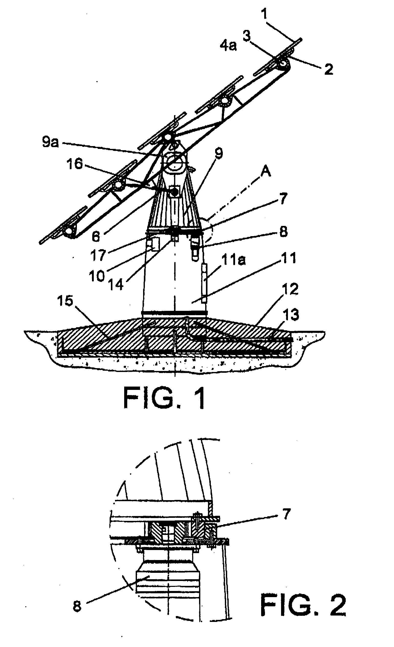
[0017] The present invention has therefore conceived a solar 10 tracker having the object of solving the previously discussed drawbacks, designed with the best installation conditions so that it provides the photovoltaic panel, a key element in the installation, with maximum protection and effectiveness during its useful life.

[0018] To that end the solar tracker is configured such that at its top portion the photovoltaic panels are placed in rows arranged in a spaced manner at different levels and on two slopes, leaving enough space between them so that no shadows are produced between panels at sunrise or at mid-day, allowing the subsequent installation, i.e. in an expansion phase, of the rows located at the ends.

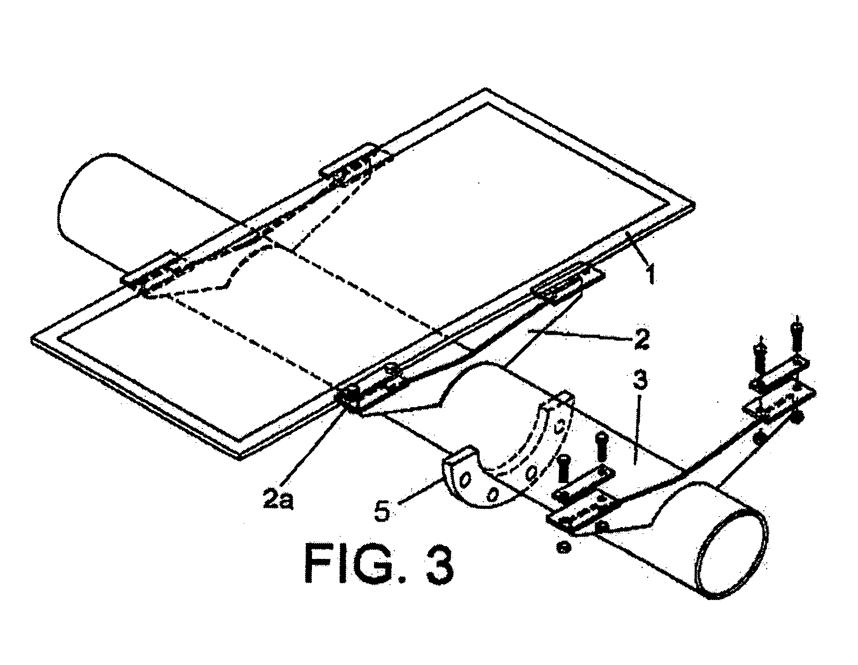
[0019] Each panel is supported by yokes to which the panel is anchored by means of clips screwed to the frame, these clips in turn being secured in a locked manner to a support pipe and spaced from one another according to the width of the panel, the support pipes with th...


PUM


Abstract

The invention relates to a solar tracker characterized by having photovoltaic panels arranged in spaced rows at different levels and two slopes, favouring their ventilation and the expansion of the frame; the panels being fixed by means of yokes and clips to a support (3) anchored to the H-shaped frame (4) resting on swivelling supports of a tower having little height supporting the entire structure, its tilt being variable by means of a tension device, the side longitudinal beams (4a) being extendible to house more rows of panels (1) since the remaining structural components, tower, bearings, column and base have been oversized for that purpose.

Description

OBJECT OF THE INVENTION [0001] As indicated in the title of this specification, the present invention relates to a solar tracker of the type which is used, through systems tracking the path of the sun, to improve photovoltaic panel production by capturing maximum solar energy radiation for the longest possible time, providing said function with a series of improved features and performance and / or alternatives with respect to the known art. [0002] More specifically, the invention consists of a solar tracker the structure of which, incorporating an easily accessible individual fixing system, the photovoltaic panels being aligned in rows on different levels on two slopes, with no contact between them, favouring ventilation and allowing them to freely expand and minimizing their structural resistance to wind, allows reaching large dimensions housing a larger number of photovoltaic panels. FIELD OF THE INVENTION [0003] This invention is applicable in the industry dedicated to the manufac...

Claims


Application Information

Patent Timeline
Patent Type & Authority Applications(United States)
IPC IPC(8): F24J2/38F24S50/20
CPCF24J2/38F24J2/523F24J2/542H02S20/00Y02E10/47Y02E10/50G01S3/7861F24S25/10F24S30/452F24S50/20H02S20/10H02S20/32F24S30/40
Inventor ROMEO, MANUEL LAHUERTA
Owner ROMEO MANUEL LAHUERTA
Why Eureka
Try Eureka