Tandem rotor wing rotational position control system

a technology of rotational position control and tandem rotor wings, which is applied in the direction of aircraft navigation control, air-flow influencers, instruments, etc., can solve the problems of limited forward speed, disadvantages of helicopters, and limited forward speed, so as to increase the cargo carrying capacity of vtol aircraft, and reduce the weight of rotor relative speed adjustment system

Active Publication Date: 2006-03-16
THE BOEING CO
View PDF25 Cites 59 Cited by
  • Summary
  • Abstract
  • Description
  • Claims
  • Application Information

AI Technical Summary

Benefits of technology

[0011] The embodiments of the present invention provide several advantages. One such advantage is the provision of determining the relative rotational position of two or more rotors of an aircraft and adjusting that relative position to prevent a collision therebetween.
[0012] Another advantage provided by an embodiment of the present invention is the provision of performing the above stated advantage through the use of elect...

Problems solved by technology

Unfortunately, helicopters do have disadvantages that are not generally associated with the other passenger and cargo transporting style aircraft.
One main disadvantage of a helicopter is a limited forward speed.
The forward speed is limited due to a limit in available power to satisfy the significantly increasing power demands or requirements needed as forward airspeed increases.
Since the airspeed is faster than the rotational speed of the rotor the rotor begins to “stall”, in the stated section, and results in a large increase in rotor drag and therefore increased power is required.
When the combination of the rotational velocity and the forward velocity exceed a drag divergence Mach number of a corresponding airfoil of th...

Method used


Image

  • Tandem rotor wing rotational position control system
  • Tandem rotor wing rotational position control system
  • Tandem rotor wing rotational position control system

Examples


Embodiment Construction

[0018] In each of the following Figures, the same reference numerals are used to refer to the same components. While the present invention is described with respect to a system for controlling the rotational position of tandem rotor wings or dual rotors of a rotorcraft, the present invention may be adapted for various applications and systems known in the art.

[0019] In the following description, various operating parameters and components are described for one constructed embodiment. These specific parameters and components are included as examples and are not meant to be limiting.

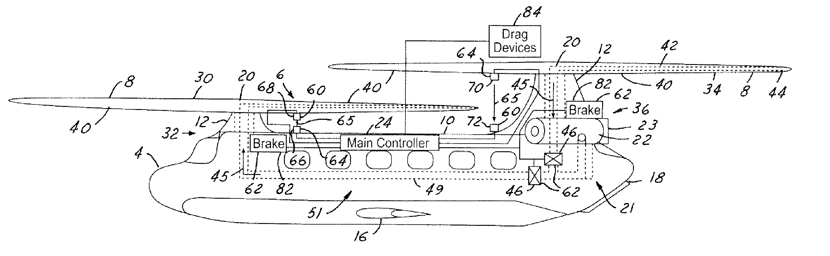
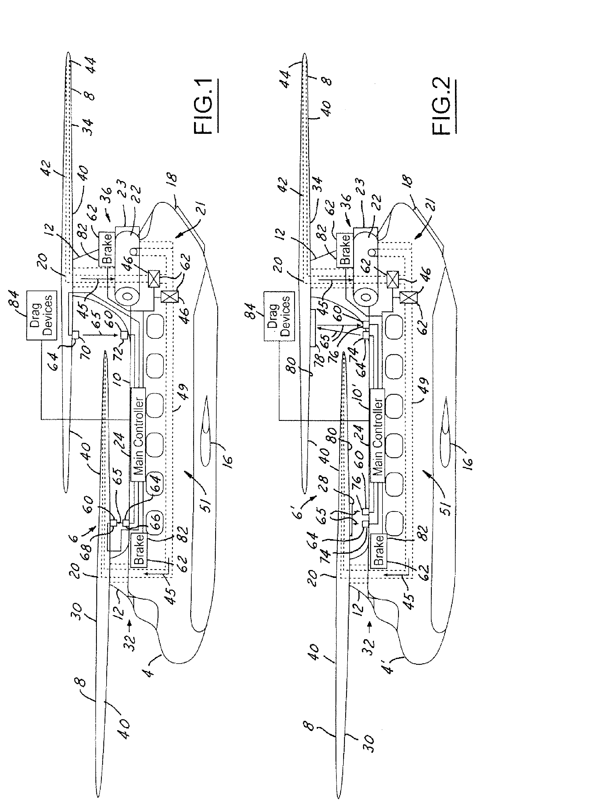
[0020] Referring now to FIGS. 1 and 2, side views of vertical takeoff and landing (VTOL) aircraft 4 and 4′ utilizing rotor rotational position-adjusting systems 6 and 6′ in accordance with an embodiment of the present invention is shown. The rotational position-adjusting systems 6 and 6′ are used to monitor and maintain appropriate rotational positioning of each of the tandem rotor / wings 8 in relation ...


PUM


Abstract

A rotational position-adjusting system (6) for a vertical takeoff and landing aircraft (4). The system (6) includes multiple detectors (60) that generate rotor signals. The rotor signals are indicative of the position of each rotor (8) of the aircraft (4). The rotors (8) provide lift to the aircraft (4). A controller (24) is coupled to the detectors (60) and adjusts the rotational speed of one or more of the rotors (8) in response to the rotor signals.

Description

TECHNICAL FIELD [0001] The present invention relates generally to aeronautical vehicle systems, and more particularly, to a method and system for controlling the rotational position of tandem rotor wings and dual or overlapping rotors of an aircraft. BACKGROUND OF THE INVENTION [0002] Helicopters are versatile aircraft in that they are capable of vertical lift and forward propulsion without the need of a runway, unlike most other passenger and cargo transporting style aircraft, such as propeller style airplanes and jet aircraft with a main fixed aircraft lifting wing. Unfortunately, helicopters do have disadvantages that are not generally associated with the other passenger and cargo transporting style aircraft. [0003] One main disadvantage of a helicopter is a limited forward speed. The forward speed is limited due to a limit in available power to satisfy the significantly increasing power demands or requirements needed as forward airspeed increases. One factor that contributes to ...

Claims


Application Information

Patent Timeline
IPC IPC(8): B64C27/00
CPCB64C27/57B64C27/08B64C27/26B64C27/24B64C27/18
Inventor RICHARDSON, STEVEN D.
Owner THE BOEING CO
Why Eureka
Try Eureka