Light emitting device and method of producing same

a technology of light emitting devices and light-gathering power, which is applied in the manufacture of semiconductor/solid-state devices, semiconductor devices, electrical devices, etc., can solve the problems of damage to light-emitting elements, inability to obtain high reflection efficiency, and inability to obtain light-gathering power, so as to prevent damage and enhance light-gathering efficiency

Inactive Publication Date: 2006-03-16
TOYODA GOSEI CO LTD
View PDF7 Cites 65 Cited by
  • Summary
  • Abstract
  • Description
  • Claims
  • Application Information

AI Technical Summary

Benefits of technology

[0025] It is an object of the present invention to provide a light emitting device capable of preventing damage caused by thermal expansion and high temperatu...

Problems solved by technology

Since the glass has high viscosity, it is necessary to increase the working temperature, and there is an adverse possibility that the light emitting element is damaged.
Further, if the reflection film 110 in the recess 101A is made of aluminum, since it metallic absorbs light, high reflection efficiency can not be obtained.
When white resin is used for the resin portion, light-gathering power can not be obtained, and sufficient lig...

Method used


Image

  • Light emitting device and method of producing same
  • Light emitting device and method of producing same
  • Light emitting device and method of producing same

Examples


first embodiment

(Structure of Light Emitting Device)

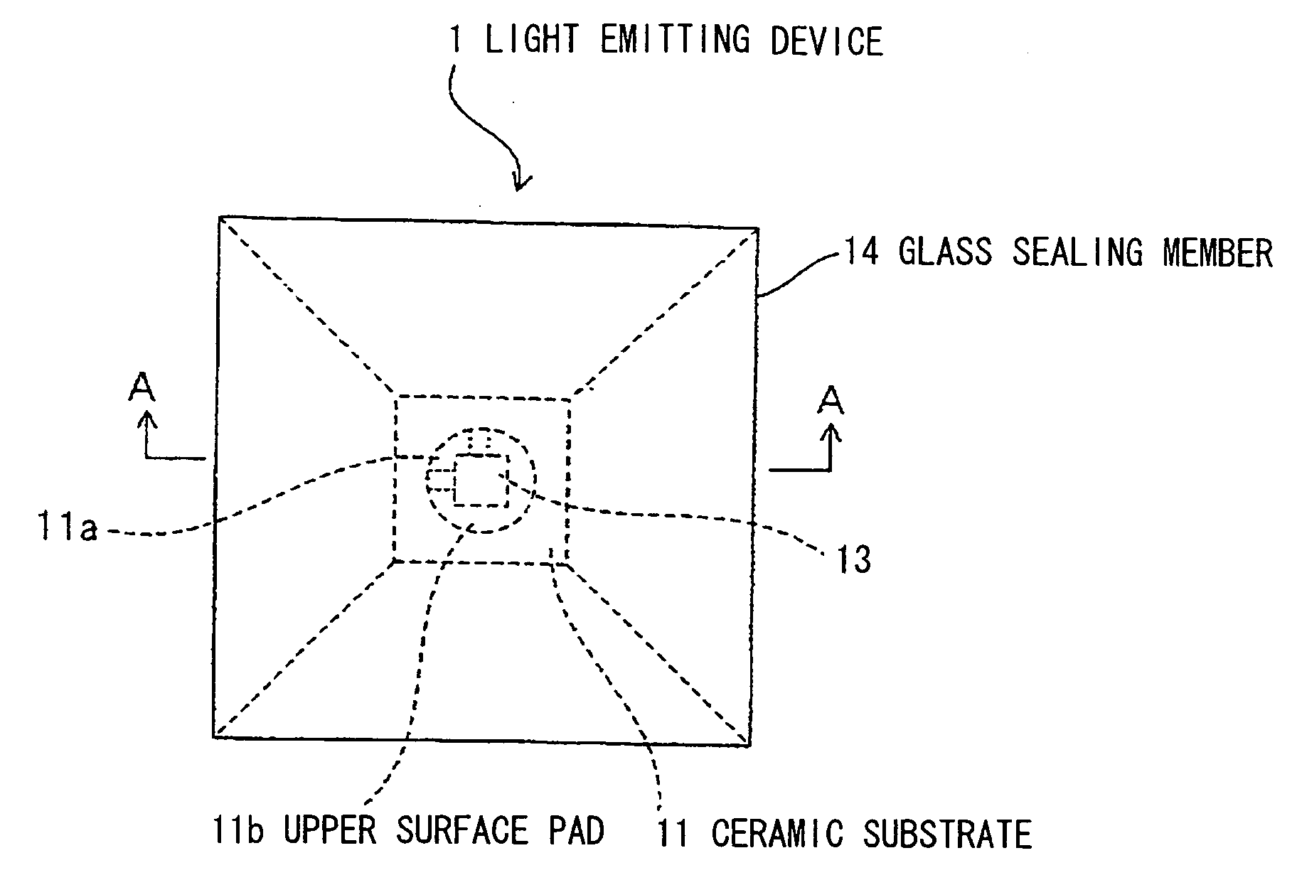
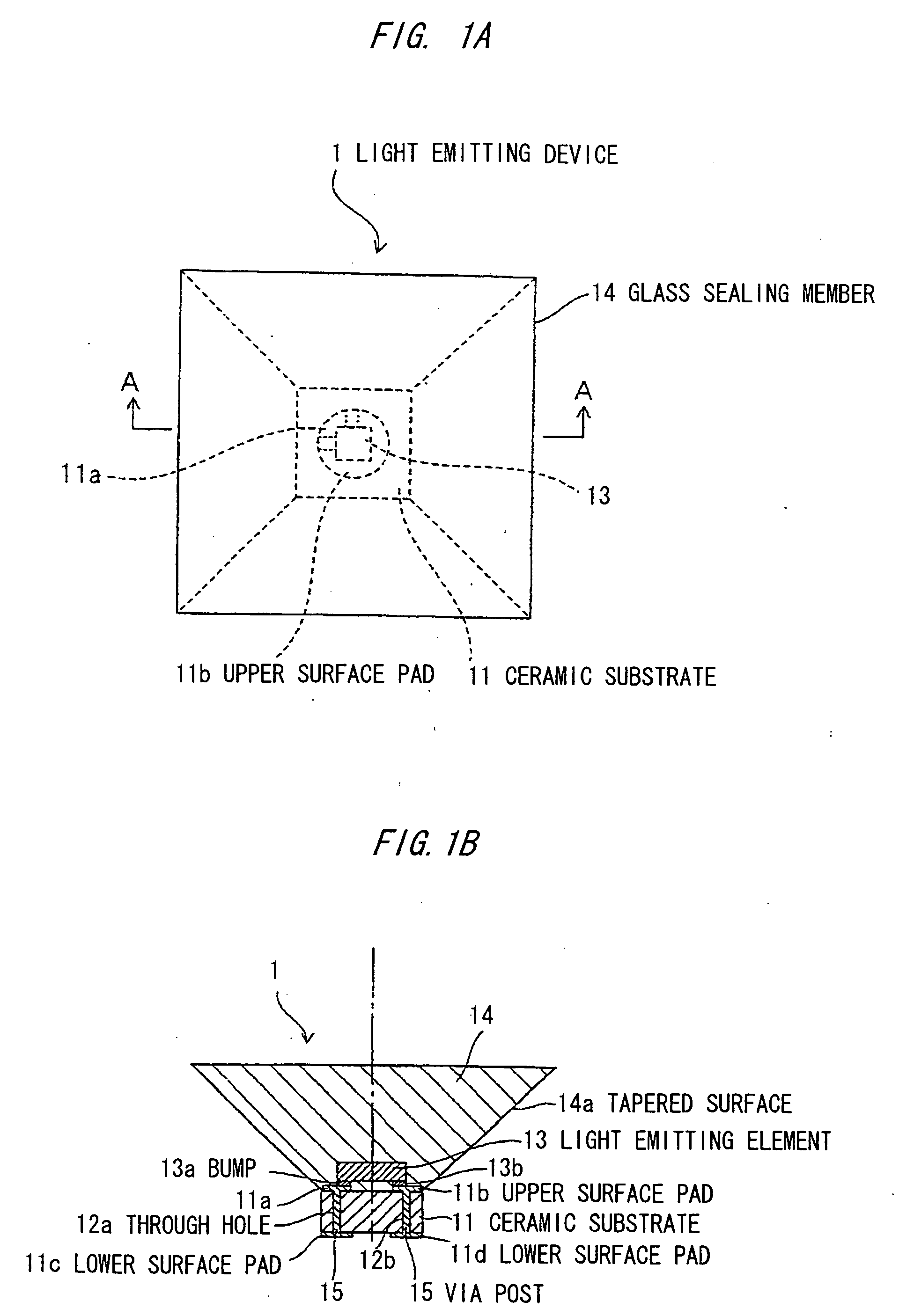
[0089]FIG. 1A is a plan view showing a light emitting device according to a first embodiment, and FIG. 1B is a sectional view taken along the line A-A in FIG. 1A.

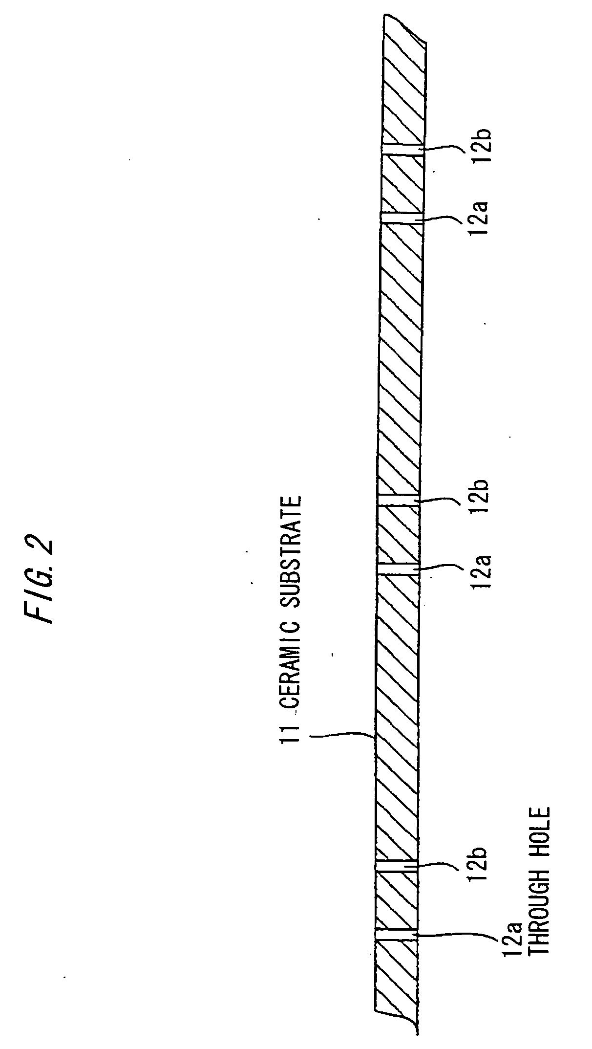
[0090] A light emitting device 1 includes a ceramic (Al2O3 including glass) substrate 11 formed with upper surface pads 11a and 11b and lower surface pads 11c and 11d, through holes 12a and 12b formed in the ceramic substrate 11 and into which via posts 15 made of Cu are embedded, a light emitting element 13 which is mounted on and connected to the upper surface pads 11a and 11b connected to the through holes 12a and 12b through bumps 13a and 13b, and a glass sealing member 14 which is sealed in a form of a reversed triangular shape such as to cover exposed portions on upper surfaces of the light emitting element 13 and the ceramic substrate 11.

[0091] In addition to Al2O3 including glass, it is possible to use Al2O2, AlN and the like as a material for the ceramic substrate 11.

[0092] ...

second embodiment

Effect of Second Embodiment

[0123] According to the second embodiment, since the predetermined portion of the upper portion of the tapered surface 14a is cut, the light emitting device 1 can be reduced in size in addition to the effect obtained in the first embodiment.

[0124] In the second embodiment, the outer surface of the glass sealing member 14 can be coated with a transparent film having lower index of refraction than that of the glass sealing member 14. With this, even if there is contamination of the tapered surface 14a of the glass sealing member 14, the index of refraction is not lowered and thus, the light extraction efficiency from the light emitting element 13 can be stabilized.

[0125] The light emitting element 13 is mounted on the ceramic substrate 11 as shown in FIG. 4. Then, they may be separated from each other and may be set in a glass mold and may be brought into a state shown in FIG. 9. That is, an optical surface may be formed by an upper surface flat surface fo...

third embodiment

Effect of Third Embodiment

[0128] According to the third embodiment, since the white resin portion 30 is provided, the same function as that obtained when the side surface of the glass sealing member 14 is provided with the reflection film can be obtained. Further, absorption of reflection of metal is not generated unlike the aluminum reflection film, blackening is not generated unlike the silver reflection film and thus, it is possible to prevent the light emitting output of the light emitting device 1 from being lowered. Other effects are the same as those of the second embodiment.

[0129] In the third embodiment, instead of providing the white resin portion 30, it is also possible to coat the side surface of the glass sealing member 14 with a transparent resin having index of refraction n of 1.4, and the surface of the transparent resin coat with white resin coat having index of refraction n of 1.5. With this, the effect of total reflection generated by coating of n=1.4 can partial...


PUM


Abstract

A light emitting device having: a light emitting element; an electricity supply portion on which the light emitting element is mounted and which supplies electricity; and an inorganic sealing material for sealing the light emitting element. The inorganic sealing material has a tapered surface which becomes wider outward in a side surface direction with respect to a center axis of the light emitting element.

Description

[0001] The present application is based on Japanese patent application Nos. 2004-262906 and 2005-210623, the entire contents of which are incorporated herein by reference. BACKGROUND OF THE INVENTION [0002] 1. Field of the Invention [0003] The present invention relates to a light emitting device capable of preventing damage caused by thermal expansion and high temperature which are ascribable to a sealing material, and capable of enhancing light extracting efficiency, and the invention also relates to a method of producing the light emitting device. [0004] The invention also relates to a light emitting device having a phosphor layer on the light emitting side and in which an LED element is sealed with a glass sealing member, and the invention also relates to a method of producing the light emitting device. [0005] Herein, a light emitting element is also referred to as LED element. [0006] 2. Description of the Related Art [0007] Japanese Patent Application Laid-open No. 2002-314142 d...

Claims


Application Information

Patent Timeline
IPC IPC(8): H01L33/00H01L33/54H01L33/56H01L33/60
CPCH01L24/97H01L2924/01005H01L33/56H01L33/60H01L2224/16225H01L2224/32245H01L2224/48091H01L2224/48247H01L2224/73265H01L2224/97H01L2924/01013H01L2924/01029H01L2924/01047H01L2924/01079H01L2924/01082H01L2924/09701H01L33/54H01L2924/01006H01L2924/12041H01L2924/01075H01L2924/01074H01L2924/01045H01L2924/01033H01L2924/01023H01L2924/00014H01L2224/81H01L2924/00H01L2224/0554H01L2224/05568H01L2224/05573H01L2224/05624H01L2924/15787H01L2924/181H01L2924/00012H01L2224/05599H01L2224/0555H01L2224/0556
Inventor HADAME, KUNIHIROSUEHIRO, YOSHINOBU
Owner TOYODA GOSEI CO LTD
Why Eureka
Try Eureka