Video surveillance camera

a video surveillance and camera technology, applied in the field of video surveillance cameras, can solve the problems of noise being introduced into the video signal, unsatisfactory heat generated by the image sensor itself, additional costs and design issues, etc., to minimize the heat generated by the processor electronics, minimize the physical contact, and minimize the effect of conta

Active Publication Date: 2006-03-16
PELCO INC
View PDF6 Cites 33 Cited by
  • Summary
  • Abstract
  • Description
  • Claims
  • Application Information

AI Technical Summary

Benefits of technology

[0006] In accordance with the present invention there is provided a video surveillance camera comprising an image sensor, first housing, second housing, electronic circuit, and thermal barrier. The image sensor is located in the first housing, and the electronic circuit is located in the second housing. The thermal barrier has first and second sides with the first side located adjacent to the first housing and the second side located adjacent to the second housing. The image sensor and other electronics, such as the processor board associated with the image sensor or the camera power supply, are located in separate housings or chambers that are separated and insulated from each other by a thermal barrier, thereby minimizing the heat generated by the processor electronics or power supply from being transferred to the area of the image sensor.
[0007] Various embodiments of the present invention include additional heat minimizing aspects of the design. The thermal barrier can have small raised areas that minimize the physical contact between the first housing and the thermal barrier. Guides through the second housing or chamber minimize contact with the fasteners that secure the camera together. These guides can extend out and away from the walls of the housing to minimize heat transfer to the fasteners. In addition, the guides can be cylindrical with a portion of the cylinder missing to further reduce any heat transfer to the fasteners. Moreover, the fasteners can be thermally insulated, for example, by being nylon coated.
[0008] In still other embodiments of the present invention, heat transfer to the image sensor area is reduced by providing raised areas on the thermal barrier to minimize contact between the thermal barrier

Problems solved by technology

The undesirable heat may be generated by the image sensor itself or by other components in the camera, such as the processor board for the image sensor or the camera power supply.
The elevated temperature can result in noise being introduced into the video signal.
However, each of these solutions requires that additional compo

Method used


Image

  • Video surveillance camera
  • Video surveillance camera
  • Video surveillance camera

Examples


Embodiment Construction

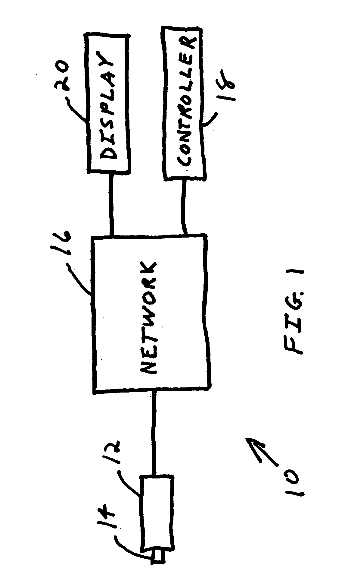
[0022] Referring to FIG. 1, a video surveillance system 10 utilizing the present invention is shown in block diagram form. Video surveillance system 10 comprises a camera 12 having a lens 14. Camera 12 is connected to network 16, which can be a closed network, local area network or wide area network, such as the Internet. A controller 18 is connected to network 16 to control video surveillance system 10 as is known in the art. The video images captured by camera 12 can be viewed by the user on display 20. Video surveillance system 10 can comprise a plurality of video cameras, video recorders, and other surveillance devices as is known in the art.

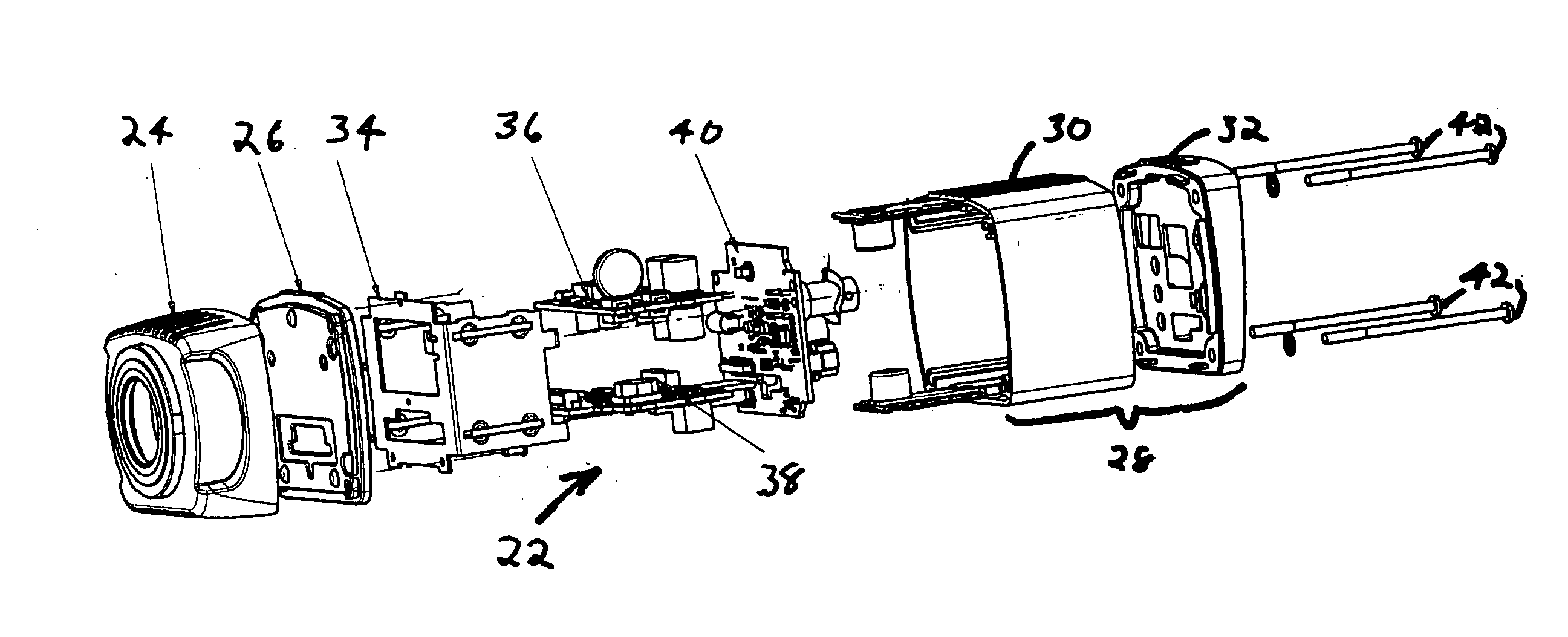
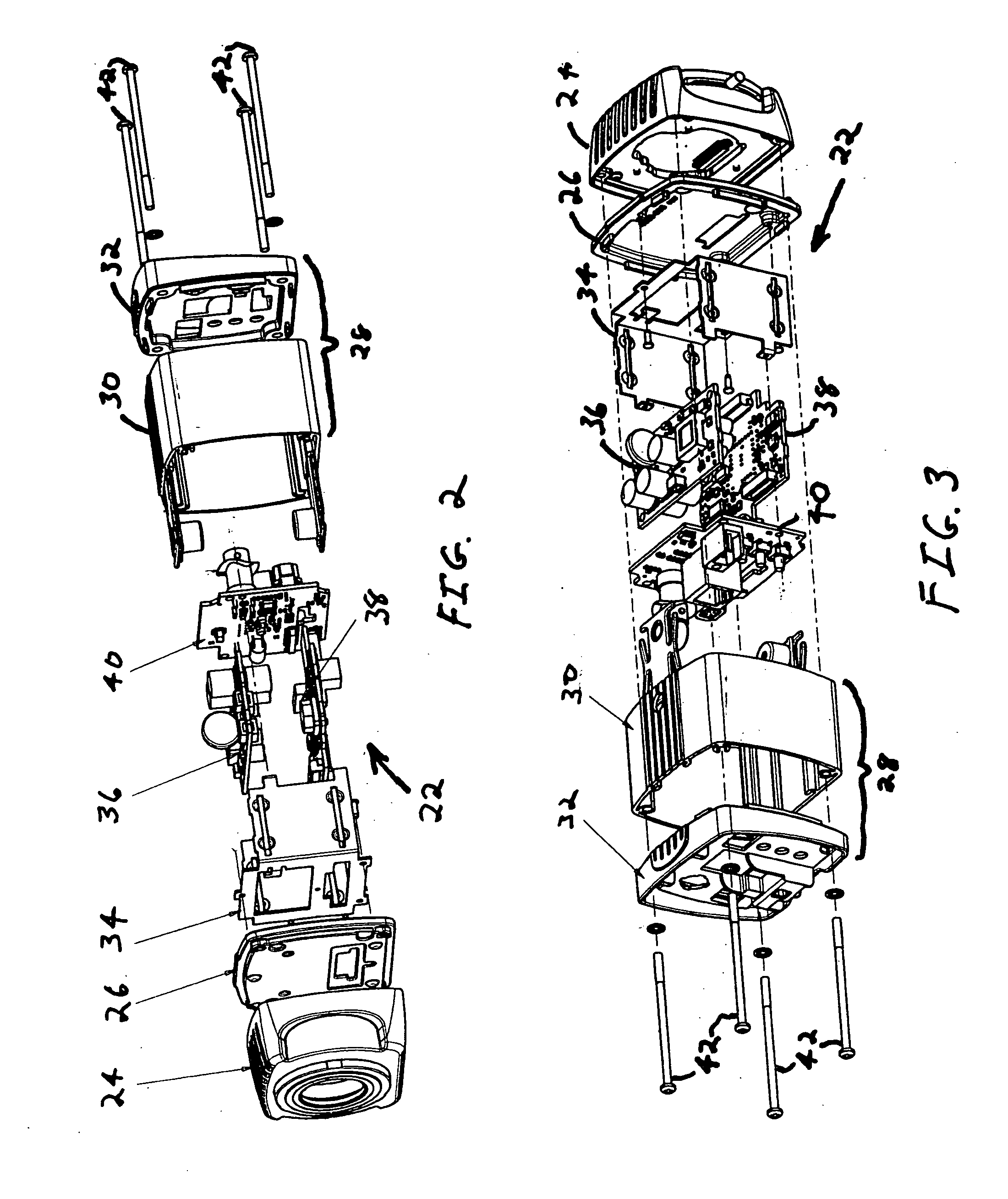
[0023] Referring to FIGS. 2 and 3, a video surveillance camera 22 has a first housing 24, thermal barrier 26, and second housing 28. First housing 24 contains a back focus assembly which is discussed in detail with reference to FIGS. 5-7. Second housing 28 consists of body 30 and rear case 32. Chassis 34 is positioned inside second housing ...


PUM


Abstract

A video surveillance camera comprising an image sensor, first housing, second housing, electronic circuit, and thermal barrier. The image sensor is located in the first housing, and the electronic circuit is located in the second housing. The thermal barrier has first and second sides with the first side located adjacent to the first housing and the second side located adjacent to the second housing. The image sensor and other electronics, such as the processor board associated with the image sensor or the camera power supply, are located in separate housings or chambers that are separated and insulated from each other by a thermal barrier, thereby minimizing the heat generated by the processor electronics or power supply from being transferred to the area of the image sensor.

Description

CROSS-REFERENCE TO RELATED APPLICATION [0001] N / A STATEMENT REGARDING FEDERALLY SPONSORED RESEARCH OR DEVELOPMENT [0002] N / A BACKGROUND OF THE INVENTION [0003] The present invention relates to video surveillance cameras and, more particularly, to a video surveillance camera having a housing structure that minimizes heat in the area of the image sensor. [0004] Video surveillance cameras must be able to provide clear and distinct images since such images may be used for security, evidentiary, identification, or other similar purposes. Image sensors, such as complementary metal oxide semiconductor (CMOS) image sensors used in video surveillance camera are sensitive to temperature. Heat can distort the video signal produced by such sensors. The undesirable heat may be generated by the image sensor itself or by other components in the camera, such as the processor board for the image sensor or the camera power supply. The heat generated by the other camera components can be transferred t...

Claims


Application Information

Patent Timeline
IPC IPC(8): H04N5/225
CPCG08B13/19619H04N5/2253H04N5/2252H04N23/51H04N23/54
Inventor LYON, THOMASPOKROVSKY, ALEXTEWS, ERIKJOHNSON, MARK J.
Owner PELCO INC
Why Eureka
Try Eureka