Micro lens array, optical member and method of producing micro lens array

Inactive Publication Date: 2006-03-16
FUJIFILM CORP +1
View PDF16 Cites 25 Cited by
  • Summary
  • Abstract
  • Description
  • Claims
  • Application Information

AI Technical Summary

Benefits of technology

[0023] Further, when the stress control film is formed as light-shielding film, light transmitted through the substrate outside the periphery of the micro lenses can be cut, whereby generation of stray light can be prevented. When the light-shielding film is provided with plating which projects in a direction parallel to the surface of the film to be opposed to the periphery of the micro lens and to narrow the effective aperture of the micro lens, light passing through the part near the periphery of the micro lenses which

Problems solved by technology

However, in the conventional micro lens array, since the micro lenses project upward from a surface of the transparent substrate, there has been a problem that a handler's hand or a jig can be brought into contact with the lens surface to damage or stain the same.
Further, when the micro lens array is bonded to another optical member, the tops of the convex micro lenses can be brought into contact wi

Method used


Image

  • Micro lens array, optical member and method of producing micro lens array
  • Micro lens array, optical member and method of producing micro lens array
  • Micro lens array, optical member and method of producing micro lens array

Examples


Embodiment Construction

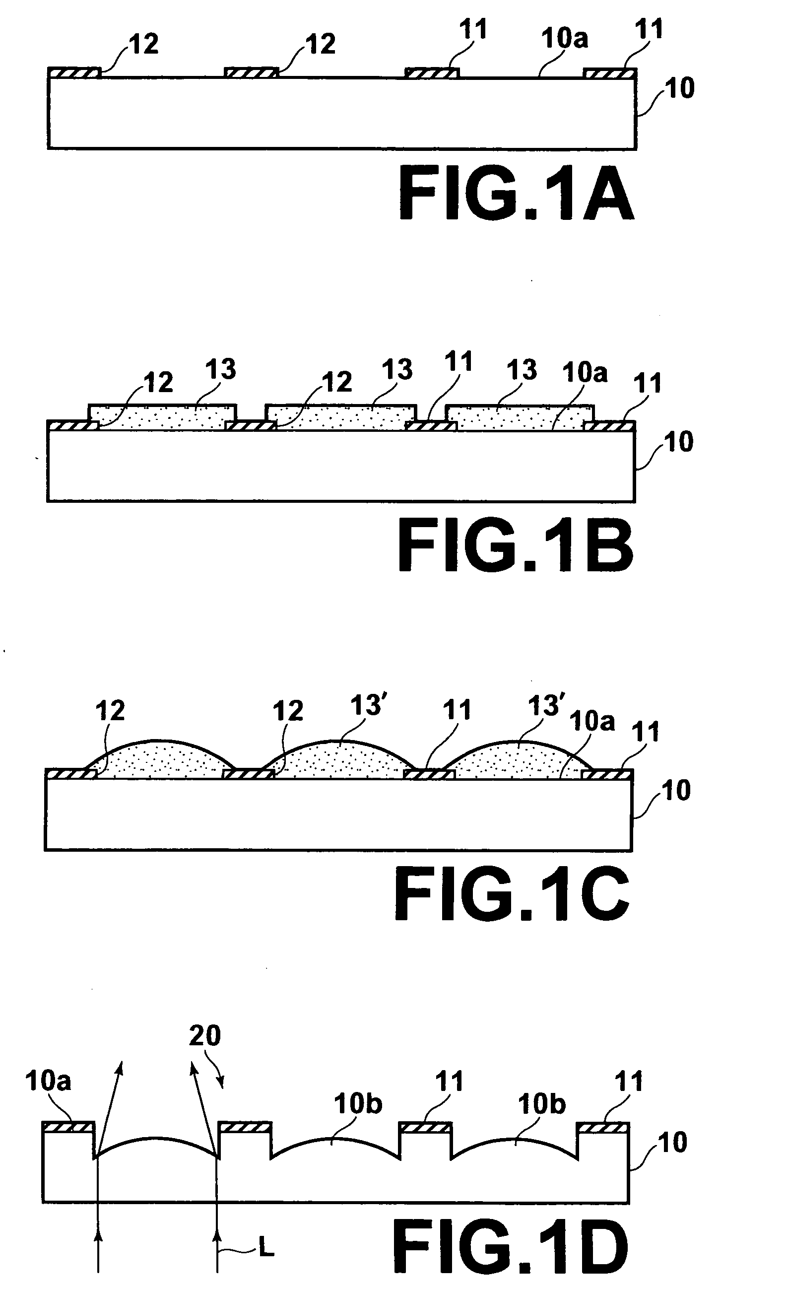
[0030] As shown in FIG. 1A, a light-shielding metal is first sputtered on a surface 10a of a transparent substrate 10, which may comprise, for instance, SiO2 glass, to form metal film 11 and a number of openings 12 are formed in the metal film 11 by usual photolithography. The metal film 11 is formed, for instance, by Cr, and the thickness thereof is about 50 to 200 nm. Further, the openings 12 are formed in the metal film 11 so that the openings 12 correspond to the pattern of a plurality of micro lenses to be produced in an array.

[0031] Then positive photoresist 13 is applied on the metal film 11 and photoresist 13 is remained in a shape corresponding to the shape of the micro lens by exposing the photoresist 13 to light through a photo mask having a pattern of openings which determine the shape of lenses and developing the same as shown FIG. 1B.

[0032] The photoresist 13 thus remained is larger than the opening 12 of the metal film 11. Further, by attaching an alignment mark on ...


PUM


Abstract

A micro lens array includes a plurality of convex micro lenses formed on a transparent substrate in an array. The micro lenses are convex toward a surface of the substrate in a position inward of the surface of the substrate and the top of the convex surface of the micro lenses is lower than the surface of the substrate.

Description

BACKGROUND OF THE INVENTION [0001] 1. Field of the Invention [0002] This invention relates to a micro lens array where a plurality of convex micro lenses are formed on a transparent substrate in an array, and an optical member using the micro lens array and to a method of producing the micro lens array. [0003] 2. Description of the Related Art [0004] There has been known a micro lens array where a plurality of convex micro lenses which are not larger than several hundred μm in their diameter are formed on a transparent substrate in an array as disclosed in, for instance, Japanese Unexamined Patent Publication No. 6(1994)-194502. Recently, the micro lens array of this type has come to be used in various fields as an optical member for forming, for instance, a liquid crystal display or a pickup for a solid state imaging system, an optical communication, or an optical disk. Since being fine in size of the micro lenses, the micro lens array is generally produced on the basis of a semico...

Claims


Application Information

Patent Timeline
IPC IPC(8): G02B27/10
CPCG02B3/0018G03F7/40G03F7/0005G02B3/0056
Inventor TSURUMA, ISAO
Owner FUJIFILM CORP
Why Eureka
Try Eureka