
Ceramic molded body and metal matrix composite

a ceramic molded body and metal matrix technology, applied in the field can solve the problems of inability to use conventional metal matrix composites, difficult to reduce the total thermal expansion coefficient of metal matrix composites,

Inactive Publication Date: 2006-03-16
HONDA MOTOR CO LTD
View PDF5 Cites 25 Cited by
  • Summary
  • Abstract
  • Description
  • Claims
  • Application Information

AI Technical Summary

Benefits of technology

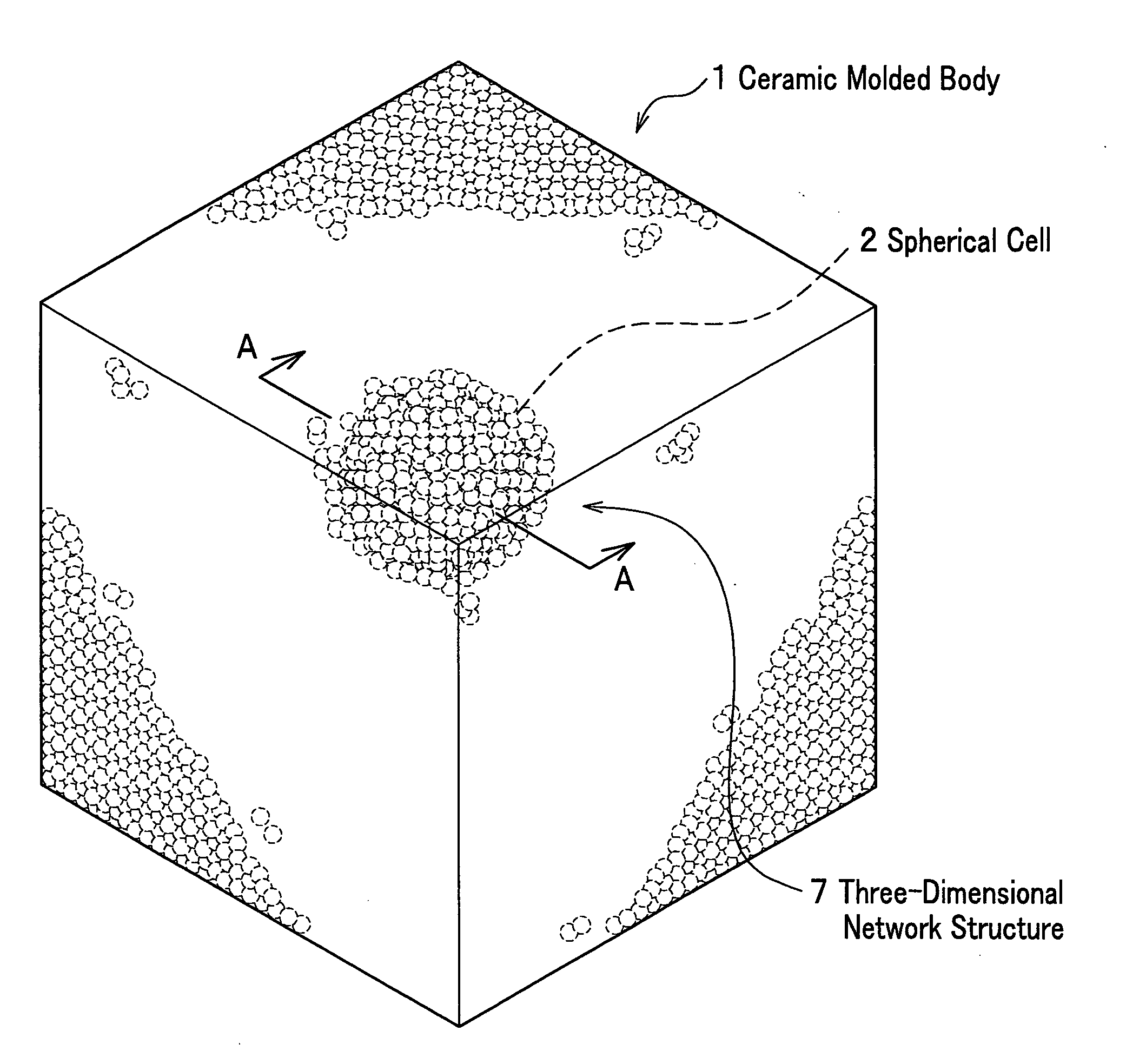
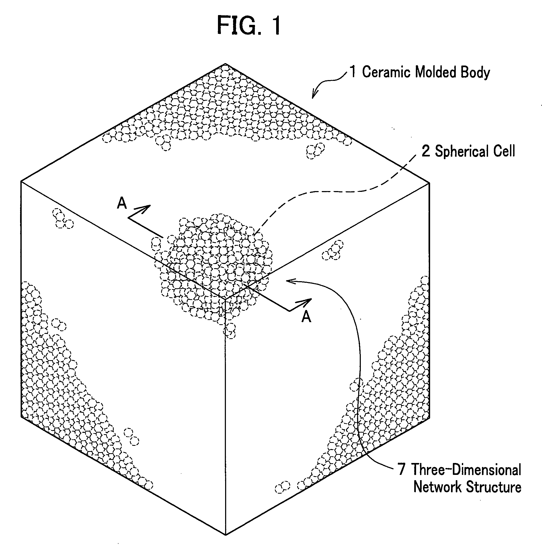
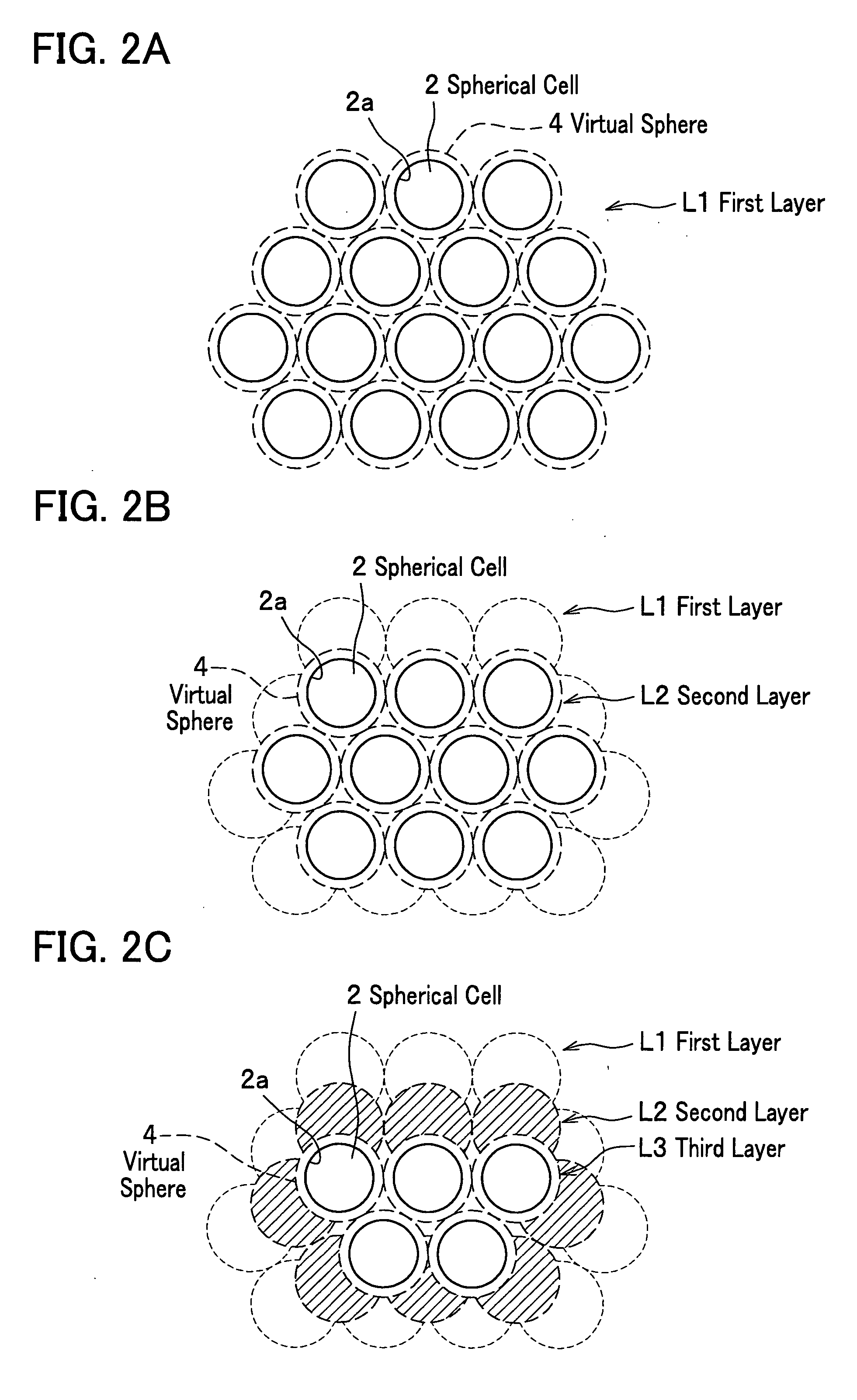
The present invention is a ceramic molded body with a three-dimensional network structure formed by spherical cells that communicate with each other through communication porosities. The ceramic molded body is used to manufacture a metal matrix composite by casting a molten metal into the spherical cells. The metal matrix composite has uniform distribution and smaller thermal expansion coefficient compared to conventional composites. The ceramic molded body with a closest-packed structural array of spherical cells reduces the volume ratio necessary for achieving a thermal expansion coefficient equivalent to that of a conventional metal matrix composite and improves the permeability of the molten metal. The metal matrix composite has the metal filled within the spherical cells and communication porosities of the ceramic molded body.

Problems solved by technology

As a result, because in the conventional metal matrix composite (for example, see the patent document 1) the anisotropy thus occurs in the thermal expansion of the metal, it becomes difficult to reduce the total thermal expansion coefficient of the metal matrix composite.
Accordingly, in spite of having an excellent mechanical strength, such the conventional metal matrix composite cannot be used as a member accompanying a large thermal change and requesting a dimensional stability.

Method used


Image

  • Ceramic molded body and metal matrix composite
  • Ceramic molded body and metal matrix composite
  • Ceramic molded body and metal matrix composite

Examples


example 1

>

(i) Preparation Process of Fine Sphere

[0068] In order to manufacture a ceramic molded body was prepared organic a fine sphere (manufactured by Soken Chemical & Engineering Co., Ltd.: product name MR-90G) consisting of a polymethylmethacrylate resin. An outer diameter of the organic fine sphere is 90 μm in a median thereof. The organic fine sphere corresponds to the fine sphere 10 in FIG. 6.

(ii) Fill Process

[0069] Next was coated a surface of the organic fine sphere with a ceramic particle (manufactured by YAKUSHIMA DENKO CO., LTD.: product name OY-20) consisting of SiC. An outer diameter of the ceramic particle is 0.5 μm in a median thereof. The ceramic particle corresponds to the ceramic particles 11 in FIG. 6. Meanwhile, coating the ceramic particle onto the surface of the organic fine sphere was performed by mixing the organic fine sphere, the ceramic particle, and polyvinyl alcohol in a constituent consisting of an organic fine sphere of 1 mass unit, a ceramic particle of ...


PUM

PropertyMeasurementUnit
inner diameteraaaaaaaaaa
temperatureaaaaaaaaaa
outer diameteraaaaaaaaaa

Abstract

The ceramic molded body of the present invention includes spherical cells of a spherical bubble plurally formed therein: in the ceramic molded body the spherical cells neighboring each other are communicated through communication porosities and form a three-dimensional network structure, and a ratio (Md / MD) of a median (Md) of inner diameters of the communication porosities to a median (MD) of inner diameters of the spherical cells is less than 0.5. In the ceramic molded body used for manufacturing a metal matrix composite, a metal is filled within the spherical cells and the communication porosities.

Description

BACKGROUND OF THE INVENTION [0001] 1. Field of the Invention [0002] The present invention relates to a metal matrix composite (MMC) and a ceramic molded body used for manufacturing the metal matrix composite. [0003] 2. Description of the Related Art [0004] Conventionally, a metal matrix composite is known where a metal is packed into a void (hereinafter referred to as “cell”) within a ceramic molded body (for example, see paragraphs 0008 to 0013 and FIGS. 6 and 10 in Japanese Patent Laid-Open Publication Hei. 6-170514 (hereinafter referred to as patent document 1)). The ceramic molded body used for the metal matrix composite is one where many porous cells are formed therein by sintering ceramic powders consisting of corundum and the like. Because the metal matrix composite obtained by filling a metal into the cell of such the ceramic molded body is excellent in mechanical strength such as an anti-wear property and the like, it is preferably used for a fine grinder plate for a paper ...

Claims


Application Information

Patent Timeline
Patent Type & Authority Applications(United States)
IPC IPC(8): B32B3/00C22C32/00
CPCB22F2998/10C04B38/0058C04B2111/00198C04B2111/00931C22C1/1036C22C2001/1021C22C2001/1073C04B35/00C04B38/0051C04B38/00B22F3/1112B22F3/26Y10T428/24997Y10T428/249967C22C1/1021C22C1/1073
Inventor YAMAMURA, SATOSHISHIBATA, KAZUOOHYA, TADASHI
Owner HONDA MOTOR CO LTD
Learn More