Ultrasonic transducer having a thin wire interface

a thin wire interface and ultrasonic transducer technology, applied in ultrasonic/sonic/infrasonic diagnostics, instruments, applications, etc., can solve the problem of extremely low signal count of cables and connectors, and achieve high integration levels

Inactive Publication Date: 2006-03-16
SONOSITE
View PDF22 Cites 56 Cited by
  • Summary
  • Abstract
  • Description
  • Claims
  • Application Information

AI Technical Summary

Benefits of technology

[0006] The present invention is directed to an ultrasound system and method which, in one embodiment, partitions the main body processing such that a portion of the processing is contained within the transducer thereby reducing the need for a multiplicity of high performance cables running between the transducer and the main body. This is possible through the use of a unique architecture to allow for proper power management given the small transducer size and an architecture that exploits the high levels of integration possible on integrated circuit technologies allowing for its implementation in a few highly integrated circuits with virtually no external components outside of the ICs.
[0007] In one embodiment, the transducer processing consists of transmitters, receivers, and the beam formers necessary to control and generate the beam formed ultrasound signal. By partitioning the system in this manner the output of the scanhead now becomes a digital data stream. All the sensitive analog signals are maintained in close proximity to their transmitters receivers and transducer elements thereby eliminating any significant signal degradation allowing increased performance. The digital data stream can also be converted to a serial high-speed bit stream to further reduce signal count across the interface. The result is a cable and connector having an extremely low signal count. Also, the signals on the cable are digital and, therefore, the cable does not require as high a fidelity, thereby further reducing the cost and size of the cable and connector.

Problems solved by technology

The result is a cable and connector having an extremely low signal count.

Method used


Image

  • Ultrasonic transducer having a thin wire interface
  • Ultrasonic transducer having a thin wire interface
  • Ultrasonic transducer having a thin wire interface

Examples


Embodiment Construction

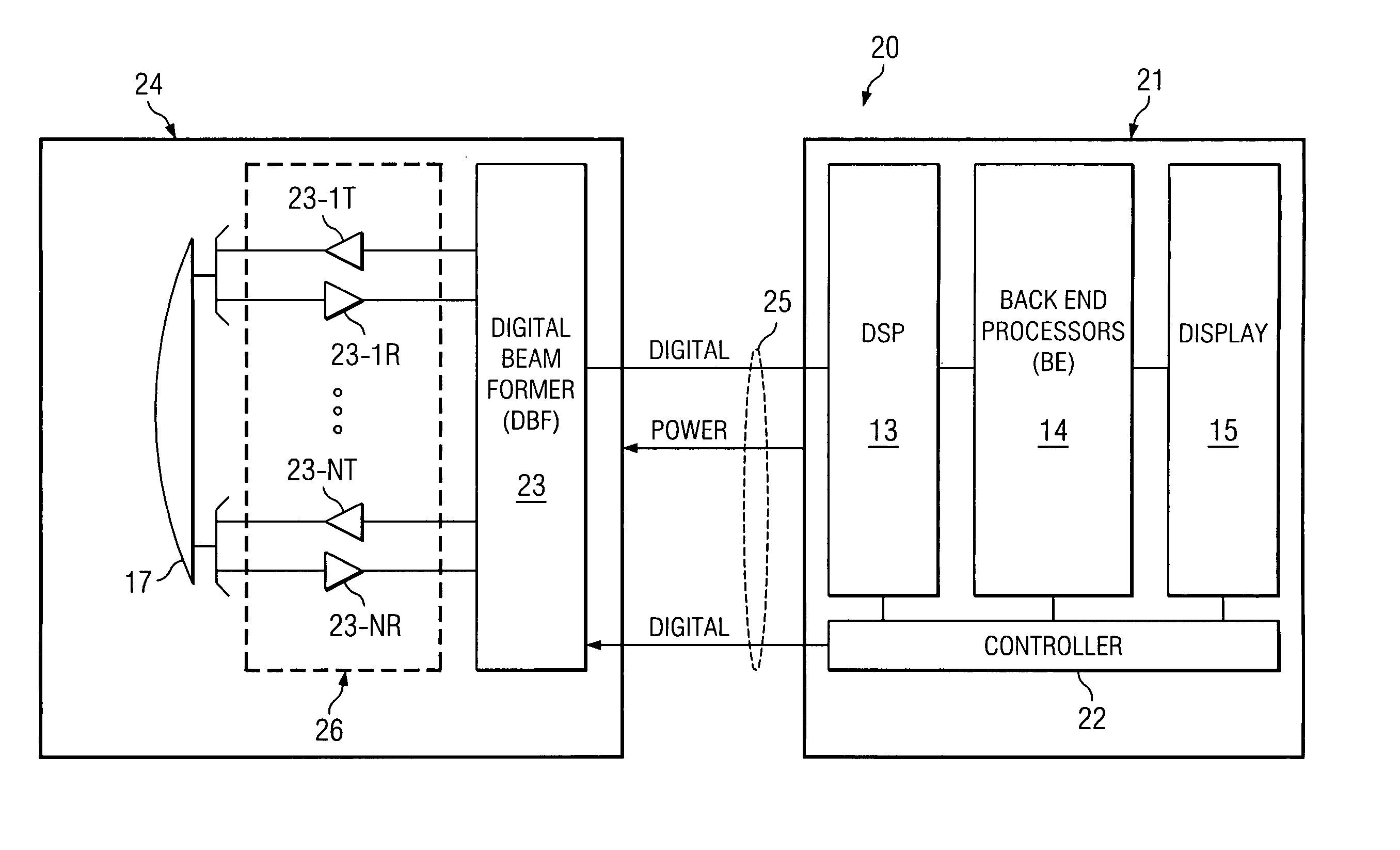
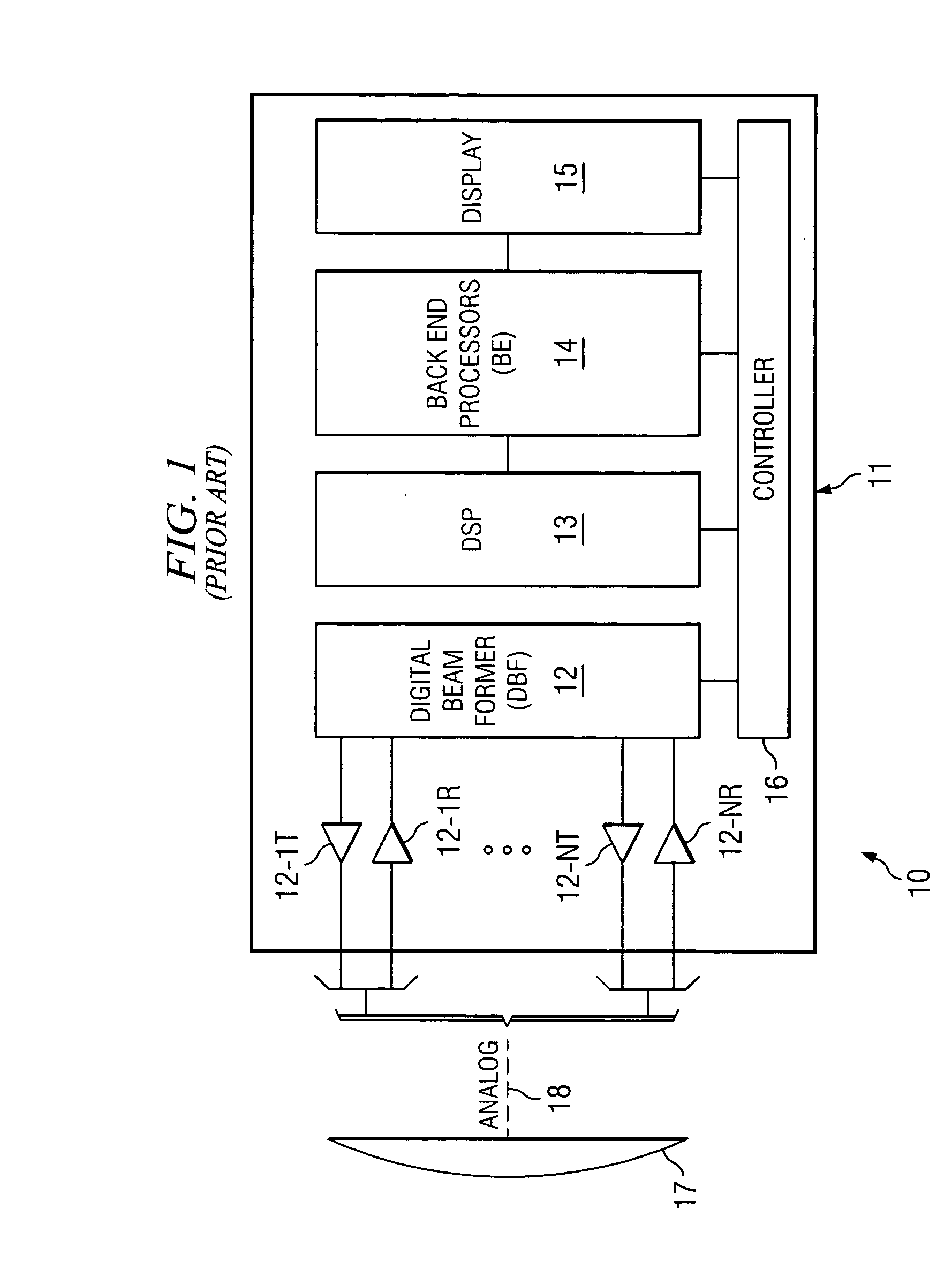
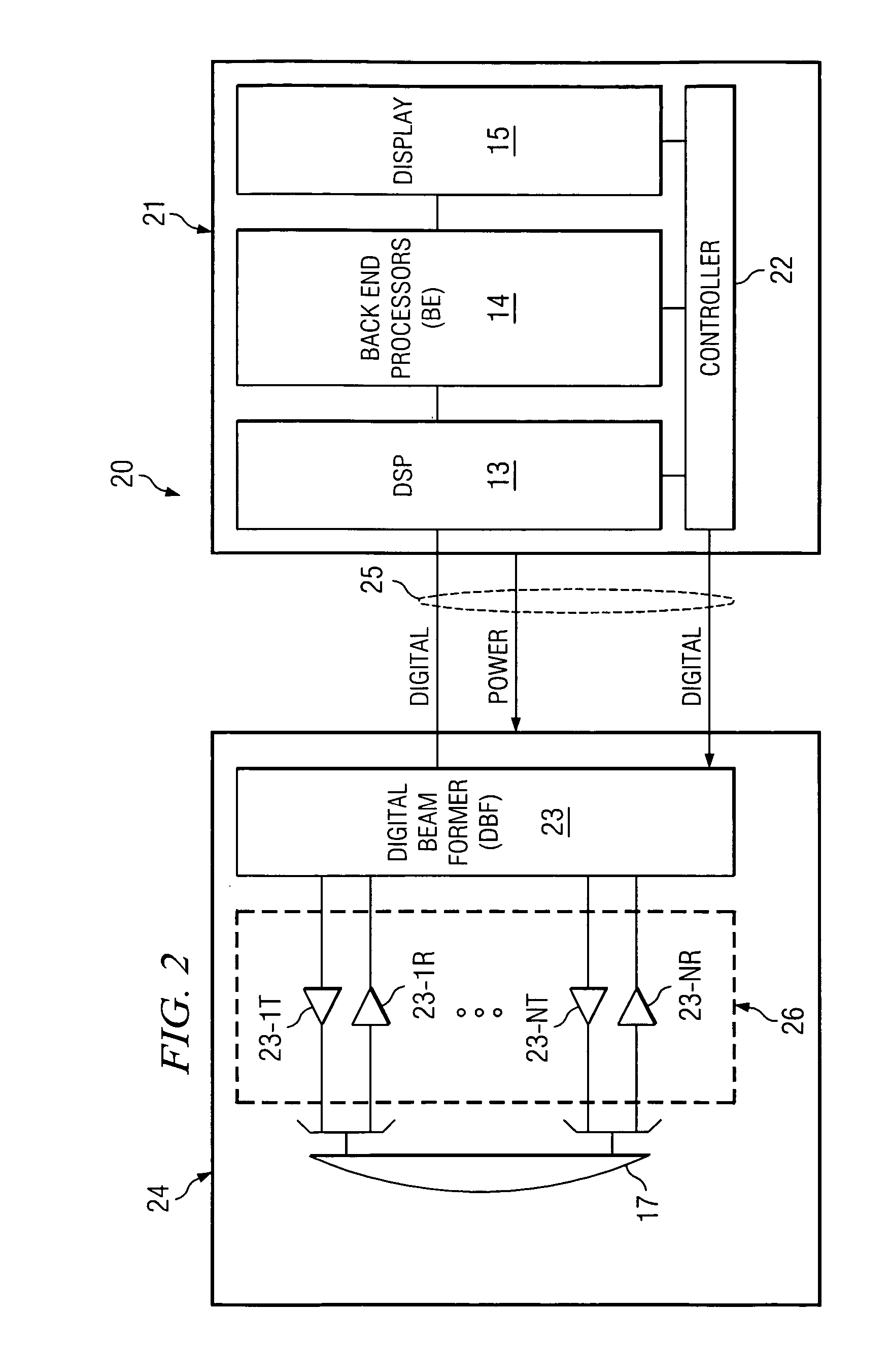
[0013]FIG. 1 shows a typical prior art architecture of an ultrasound system, such as system 10 having transducer array 17, which is coupled via analog cable 18 to individual receiving and transmit channels 12-IT, 12-IR to 12-NT, 12-NR to digital beam former 12. Typically, the Tx and Rx signals are time multiplexed. DSP 13 provides signals to and receives signals from beam former 12. Back end processing 14 then provides signals to drive display 15 all under control of controller 16. The operation of these elements can be as discussed in the above-identified '412 and '651 patents.

[0014] In this arrangement, cable 18 contains a high number of individual signals, typically carried on coax cables, usually in the order of 128 or 256 to carry the analog signals from transducer array 17 back and forth between receiving and transmit channels 12-IT, 12-IR to 12-NT, 12-NR. As discussed above, cable 18 is big, bulky, heavy, expensive and not very efficient. The analog signals are also sensitiv...


PUM


Abstract

The present invention is directed to an ultrasound system and method which, in one embodiment, partitions the main body processing such that a portion of the processing is contained within the transducer thereby reducing the need for a multiplicity of high performance cables running between the transducer and the main body. This is possible through the use of a unique architecture to allow for proper power management given the small transducer size and an architecture that exploits the high levels of integration possible on integrated circuit technologies allowing for its implementation in a few highly integrated circuits with virtually no external components outside of the ICs.

Description

CROSS-REFERENCE TO RELATED APPLICATIONS AND PATENTS [0001] The present application is related to co-pending, and commonly-assigned U.S. patent application Attorney Docket No. 65744 / P017US / 10404216, entitled “Ultra System Power Management,” filed concurrently herewith U.S. patent application Ser. No. 10 / 847,643, filed on May 17, 2004, entitled “Processing Of Medical Signals;” U.S. patent application Ser. No. 10 / 821,123, filed on Apr. 8, 2004, entitled “Systems And Methods For Providing ASICS For Use In Multiple Applications;” U.S. patent application Ser. No. 10 / 821,198, filed on Apr. 8, 2004, entitled “System And Method For Enhancing Gray Scale Output On A Color Display;” the disclosures of which are all hereby incorporated.TECHNICAL FIELD [0002] This disclosure relates to ultrasound devices and more particularly to such devices having a thin wire interface. BACKGROUND OF THE INVENTION [0003] Ultrasound medical devices are becoming more common. Their typical implementation has the tr...

Claims


Application Information

Patent Timeline
Patent Type & Authority Applications(United States)
IPC IPC(8): A61B8/00
CPCA61B8/00A61B8/4455G06T2210/08G01S7/5208G01S15/8909G01S7/52034G01S15/8915A61B8/5207A61B8/56
Inventor LITTLE, BLAKE W.
Owner SONOSITE
Why Eureka
Try Eureka