

Vapor pump power system
- Summary
- Abstract
- Description
- Claims
- Application Information
AI Technical Summary
Benefits of technology
Problems solved by technology
Method used
Image

Examples
Embodiment Construction
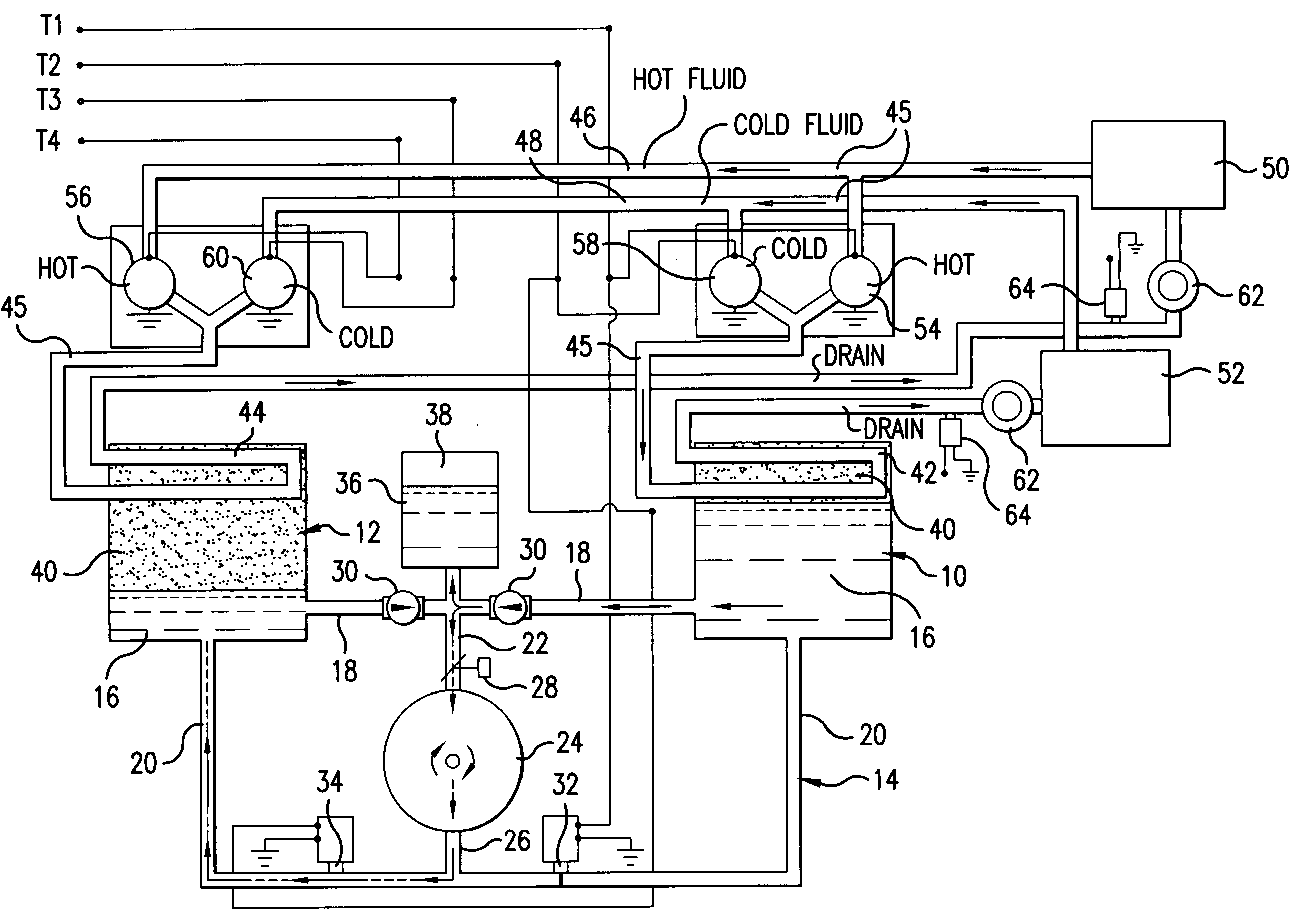
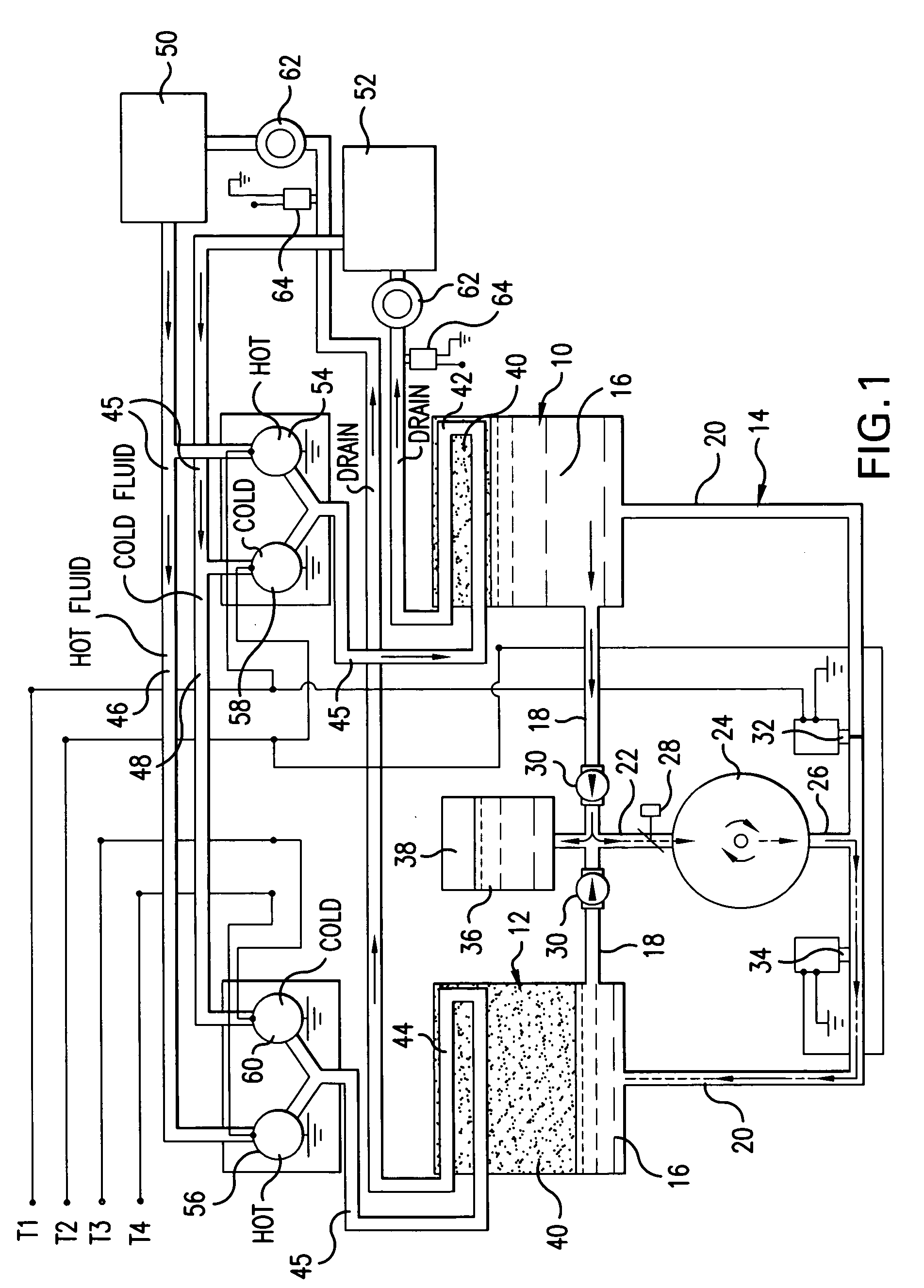
[0020] Referring to FIG. 1, the preferred embodiment constructed according to the invention includes first and second pressure vessels 10,12 that are hydraulically connected via a hydraulic conduit 14. In the preferred embodiment, two pressure vessels are employed, although additional vessels can be used in alternative embodiments. Additionally, each pressure vessel is preferably a single vessel, but alternatively, several vessels can be linked as to operate together as a single vessel.
[0021] Hydraulic fluid 16 is contained within the pressure vessels 10,12 and the conduit 14, which fluidly communicates the pressure vessels 10,12 and allows the hydraulic fluid to flow from one vessel to the other 12,10. The preferred conduit 14 includes vessel outflow portions 18 connected to each pressure vessel 10,12 to receive hydraulic fluid 16 flowing therefrom. The conduit 14 also preferably includes vessel inflow portions 20 configured to direct the hydraulic fluid 16 into each pressure vess...
PUM
 Abstract
Description
Claims
Application Information