Regenerative load bank with a motor drive

Inactive Publication Date: 2006-03-23
HAMILTON SUNDSTRAND CORP
View PDF10 Cites 14 Cited by
  • Summary
  • Abstract
  • Description
  • Claims
  • Application Information

AI Technical Summary

Benefits of technology

[0006] The invention operates as a regenerative load bank (RLB) that is a viable alternative to the resistive load bank. Rather than dissipating generated power in the resistive elements of the resistive load bank, the RLB feeds power generated by the unit under test back into the utility grid. The RLB dramatically reduces power demand from the grid during generator testing, reduces water demand otherwise required for cooling waste heat of resistive elements in the resistive load bank and reduces floor “footprint” in comparison with the resistive load bank. In addition, the RLB allows loading generator with unity, leading, or lagging PF programmable by operator and enables high fidelity emulation of various high-power electrical loads, such as typical electrical loads aboard aircraft, by modulating loading characteristics.

Problems solved by technology

However, for generator endurance testing at rated power, the resistive load bank is very inefficient since electrical energy is wasted in the resistive elements.

Method used


Image

  • Regenerative load bank with a motor drive
  • Regenerative load bank with a motor drive
  • Regenerative load bank with a motor drive

Examples


Embodiment Construction

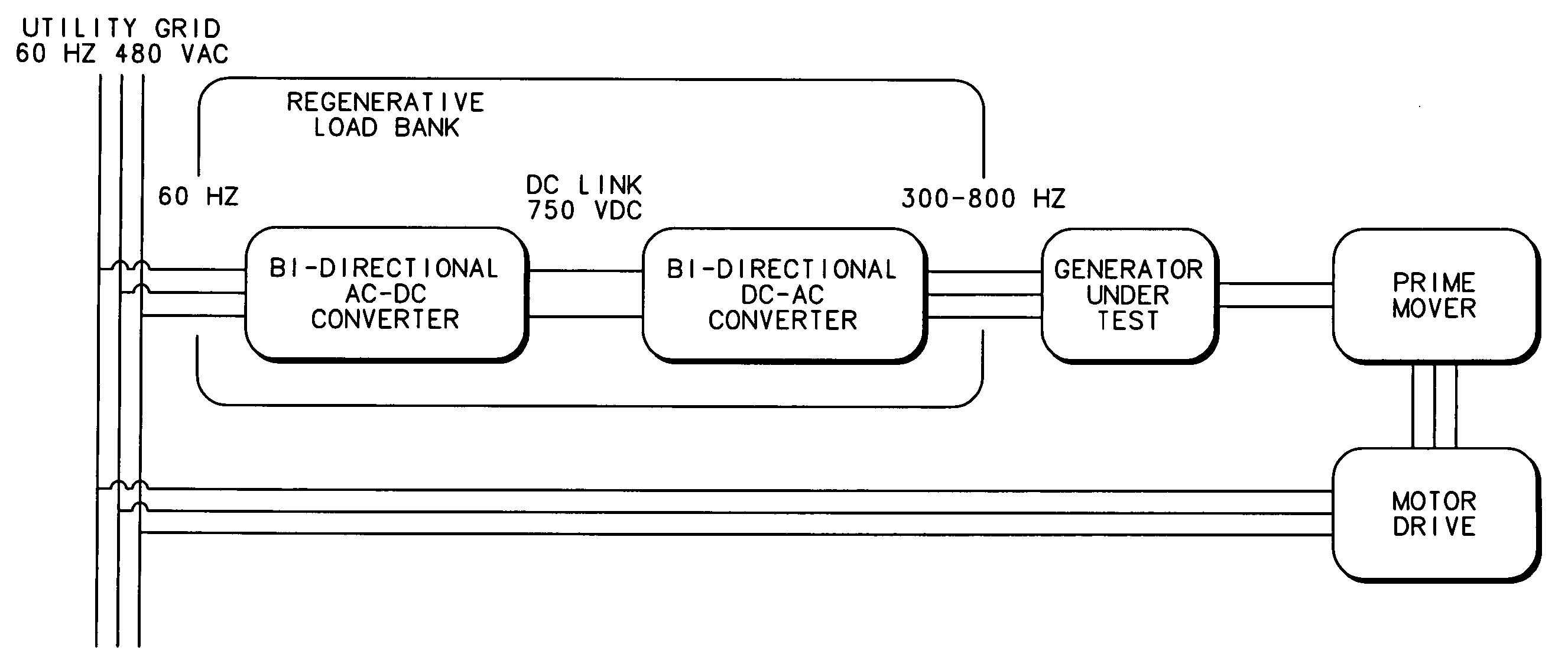
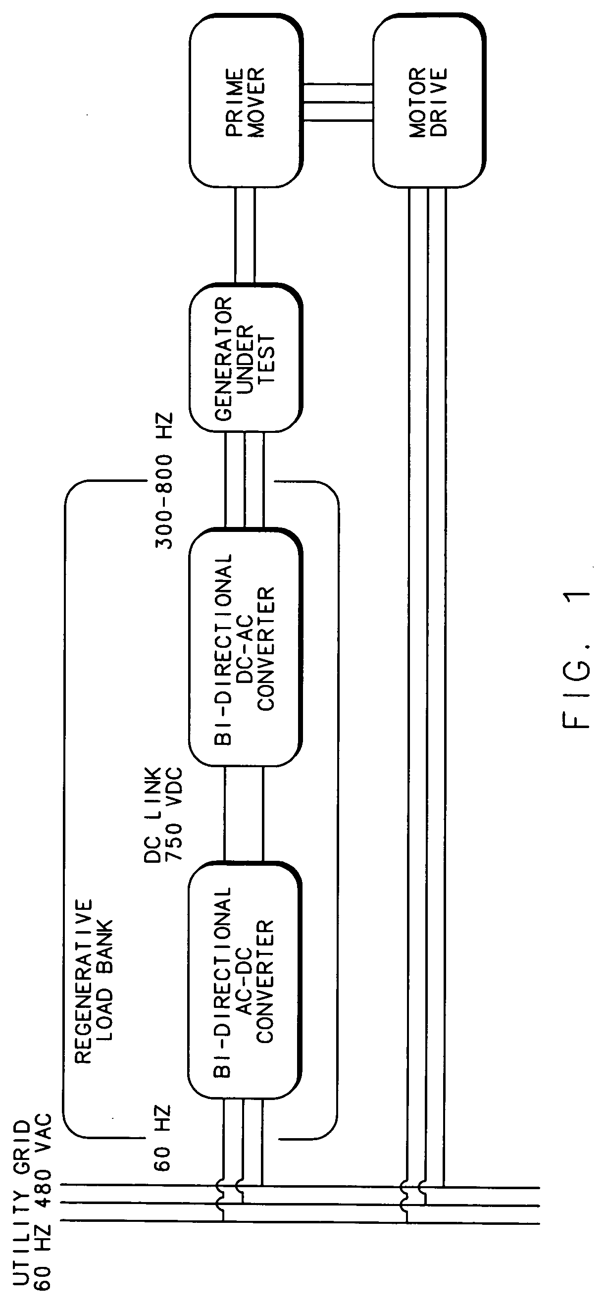
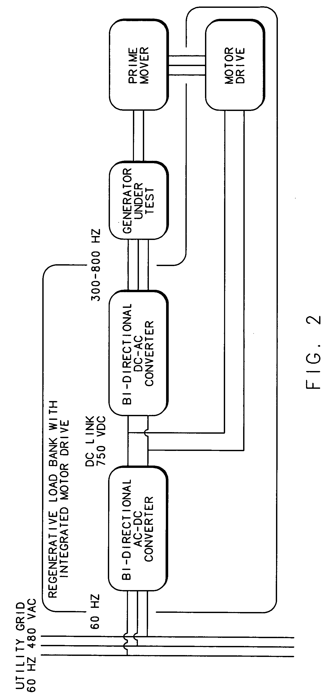
[0013]FIG. 1 shows a regenerative test stand configuration 2 with a regenerative load bank according to a preferred embodiment of the invention. A utility grid 4 supplies power, typically polyphase alternating current (AC) power of the three-phase type, as shown, to an electronic motor drive 6 by way of motor drive supply lines 8. The motor drive 6 provides suitable power to drive a prime mover 10 by way of prime mover supply lines 11.

[0014] The prime mover 10 may comprise a DC or AC motor. If the prime mover 10 comprises a DC motor, the motor drive 6 comprises a variable potential DC source. If the prime mover 10 comprises an AC motor, the motor drive 6 comprises a source of selectable variable frequency polyphase AC power, typically three-phase. If the prime mover 10 is a motor of the induction or synchronous type, the AC current supplied by the motor drive 6 is sinusoidal. If the prime mover 10 is a motor of the “brushless DC” type, the AC current supplied by the motor drive 6 i...


PUM


Abstract

An electronic power converter for a generator under test that emulates resistive and inductive-capacitive (LC) loads and regenerates energy from the generator back to a utility grid.

Description

CROSS REFERENCE TO RELATED APPLICATIONS [0001] This Application claims the benefit of the filing date for prior filed co-pending Provisional Application Ser. No. 60 / 611,380, filed 20 Sep. 2004.FIELD OF THE INVENTION [0002] The invention relates to test equipment for high power alternating current power generation equipment, and more particularly to an improved load bank system for testing high power alternating current generators. BACKGROUND OF THE INVENTION [0003] Currently, test stands are used to perform endurance tests on high power alternating current (AC) generators, such as aircraft generators. A typical test stand comprises a prime mover, a gearbox installed between the prime mover and a generator under test, a resistive load bank, a generator control unit (GCU) with associated potential and current sensors at the point-of-regulation (POR), generator cooling accessories and support instrumentation. The prime mover is commonly a direct current (DC) motor, although an AC motor...

Claims


Application Information

Patent Timeline
IPC IPC(8): B60K1/00
CPCG01R31/42H02P2101/30H02P9/30
Inventor ROZMAN, GREGORY I.
Owner HAMILTON SUNDSTRAND CORP
Why Eureka
Try Eureka