
Flash chromatography cartridge

a technology of chromatography and cartridges, which is applied in the direction of ion-exchangers, separation processes, instruments, etc., can solve the problems of leaking seams of cartridges, welded construction leakage, and high cos

Inactive Publication Date: 2006-03-23
SCI PLASTIC PRODS
View PDF25 Cites 11 Cited by
  • Summary
  • Abstract
  • Description
  • Claims
  • Application Information

AI Technical Summary

Benefits of technology

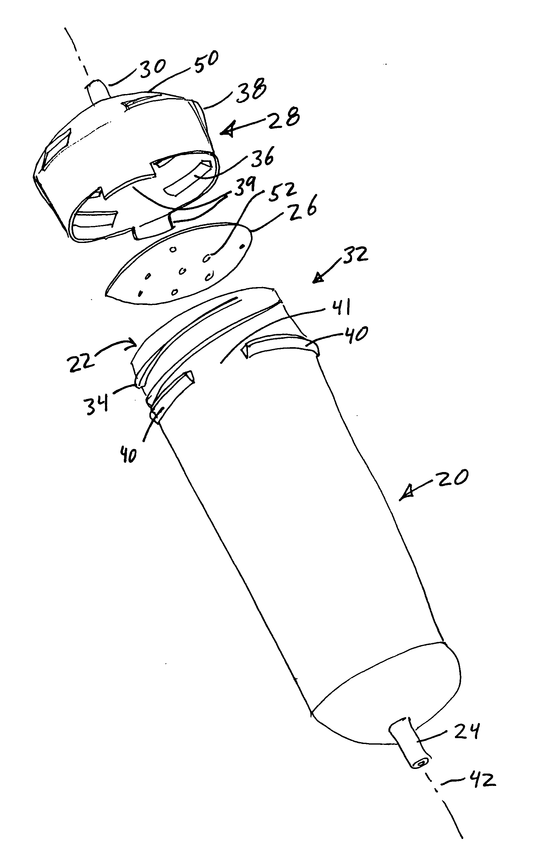
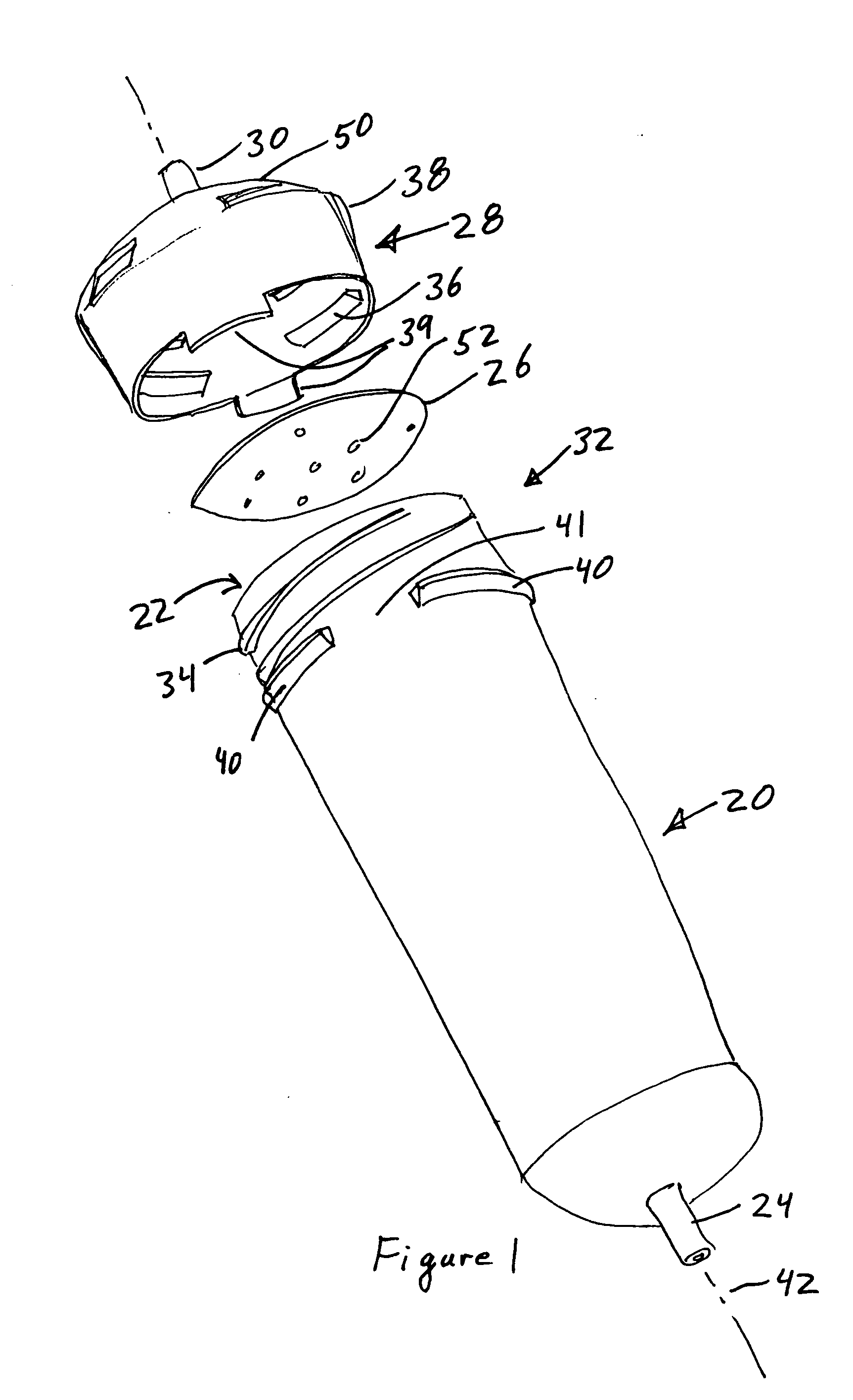
[0012] In further variations the seal comprises a resilient ring extending from a top of the cap with the seal being located and sized to engage a lip of the container. Preferably a fluid dispenser is interposed between the container and the cap. The dispenser has a plurality of fluid outlets located across a substantial portion of a cross-section of the container to dispense fluid from the inlet of the cap over the cross-section. The fluid dispenser preferably takes the form of a dish having a plurality of holes extending through the dish, so as to place the inlet and the outlet in fluid communication. Moreover, the dish preferably, but optionally has a rim placed between the cap and the container. In further embodiments the locking tab extends parallel to a longitudinal axis of the container and extends from a distal end of a skirt of the cap. Further, the inlet can take the form of a tube threadingly engaging one of the cap or container, with the tube having a threaded exterior distal end located on an exterior of the engaged one of the cap or container. Advantageously the seal and lip abut at an inclined angle with the seal extending inward toward a longitudinal axis of the container and cap. Moreover, the seal preferably joins the top of the cap at a corner which encircles a longitudinal axis of the container. Still further, the fluid dispenser has a periphery located in that corner. Preferably chromatographic packing material is placed in the cartridge by the user before the cap is locked onto the container. Preferably, but optionally, the material to be analyzed is also placed in the cartridge by the user before the cap is locked onto the container. This allows the user to custom select and place any of a plurality of different chromatographic packing materials in the container.
[0013] In a further embodiment there is provided a low pressure liquid chromatography cartridge having a tubular container adapted to receive a chromatographic packing material. The container has an outlet port located at a downstream end of the container and configured for use with chromatographic equipment during use of the cartridge. The container also has container threads formed on an upstream end of the container. A cap is provided with an inlet port located on an upstream end of the cap, with port being configured for use with chromatographic equipment during use of the cartridge. The cap also has cap threads located on the cap to threadingly engage the container threads. Locking means on the container and cap prevent manual removal of the cap. Resilient sealing means are provided for sealing the cap to the container when a user places the cap on the container and engages the locking means.

Problems solved by technology

This operating pressure is sufficiently high that these cartridges, which have relative large diameter bodies leak at the seams.
But even that welded construction will leak if there are defects in the welds.
That welded construction and the accompanying manufacturing and material costs cause in undesirably high costs, especially as the cartridges must be either discarded, or must under go extensive and thorough cleaning after a single use, or at most after a few uses with similar fluids.
Further, the welded construction requires the chromatographic packing material be placed in the cartridge before it is welded, or it requires careful packing of the column under pressure, both of which limit the usefulness of the cartridge and increase its cost.
But this interference fit is created at the factory and again creates a cartridge that does not allow the user to easily vary the contents of the cartridge.
The use of secondary cartridges increases the amount of run time and expensive solvent, due to elution of the sample.
The secondary cartridge is also an additional expense, and requires additional time for loading.
Moreover, welded cartridges are limited by being pressure rated to only about 45 psi, due to leaking and instability at higher pressures.
Further, the removal and reconnection of these various cartridges is cumbersome and time consuming, and the cost of each cartridge is expensive.
The connection and use of these Y fittings is cumbersome.

Method used


Image

  • Flash chromatography cartridge
  • Flash chromatography cartridge
  • Flash chromatography cartridge

Examples


Embodiment Construction

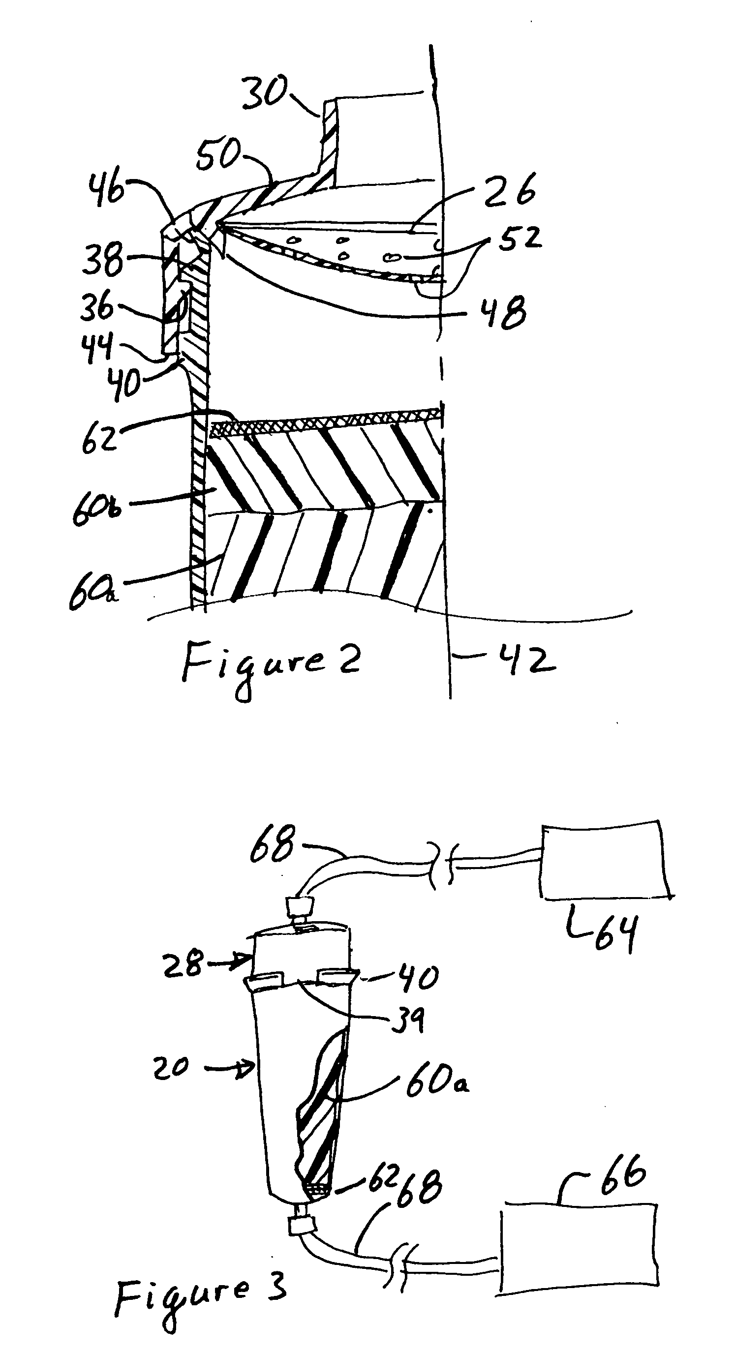
[0037] Referring to FIGS. 1-2 and 7, a cartridge is provided comprising tubular container 20 suitable for flash chromatography. The container has a cap 28 with inlet and outlet ports 24, and 30, respectively. The container 20 has an open end 22 at and upstream or proximal end, and an outlet port 24 at a downstream or distal end. A fluid dispenser 26 is placed in or upstream of the open end 22 and a cap 28 is fastened over the open end 22 and fluid dispenser. An inlet port 30 is provided on the cap 28. A locking mechanism 32 is placed on one or both of the container 20 and cap 28 to hold the cap to the container. A seal 48 between the cap 28 and container 20 is held in fluid tight compression by mating threads 32, 34 and the locking mechanism 32.

[0038] In use, the inlet 30 is placed in fluid communication with a source of fluid to be processed in a low pressure liquid chromatography (LPLC) or flash chromatography process. Processing or filtering media is placed in the container 26. ...


PUM

PropertyMeasurementUnit
interference angleaaaaaaaaaa
angleaaaaaaaaaa
angleaaaaaaaaaa

Abstract

A low pressure liquid chromatographic cartridge is provided having a tubular polymer container adapted to receive a chromatographic packing material. The container has an outlet port located at a downstream end of the container and container threads formed on an upstream end of the container. A polymer cap having cap threads located on the cap threadingly engage the container threads. An inlet port is located on an upstream end of the cap. A flange depends from the cap and mates with the lip of the container to form a fluid tight seal between the polymer cap and container suitable for use in low pressure liquid chromatography. A locking tab on a skirt of the cap engages a recess on the container when the seal engages the cap and container to lock the cap in position relative to the container. Alternatively, continuous screw threads on the cap and container may hold the parts together.

Description

CROSS-REFERENCE TO RELATED APPLICATIONS [0001] This application is a continuation-in-part of U.S. patent application Ser. No. 10 / 842,288 filed May 10, 2004, the entire contents of which are hereby incorporated by reference.BACKGROUND OF THE INVENTION [0002] This invention relates to method and apparatus involving cartridges for use in flash chromatography and low pressure liquid chromatography equipment. [0003] Chromatographic analysis passes fluids through columns containing specially treated sorbent which allows the chemicals in the fluid to be eluted at different times and thus form separated peaks on a chromatogram. In order to prepare or clean up the fluid being analyzed the fluid is often passed through a sorbent under pressure. Further, for low pressure liquid chromatography (LPLC) or flash chromatography the fluid may be passed through a sorbent at a pressure of 20-100 psi. This operating pressure is sufficiently high that these cartridges, which have relative large diameter...

Claims


Application Information

Patent Timeline
Patent Type & Authority Applications(United States)
IPC IPC(8): B01D15/08G01N30/60
CPCG01N30/6026B01D15/14G01N30/6091B01D15/165B01D15/22G01N2030/027
Inventor ELLIS, SAMUEL A.HARLAN, JEFFREY L.
Owner SCI PLASTIC PRODS
Learn More