Dry hydraulic can shaping

a technology of hydraulic cans and cans, applied in the field of hydraulic can shaping, can solve the problems of increasing reducing the number of manufacturing steps required, and increasing the production time, so as to reduce the number of manufacturing steps, increase the throughput of containers, and reduce production time

Active Publication Date: 2006-03-23
BALL METALPACK LLC
View PDF10 Cites 24 Cited by
  • Summary
  • Abstract
  • Description
  • Claims
  • Application Information

AI Technical Summary

Benefits of technology

[0006] The present invention is directed to a method of shaping aerosol containers. A method of the invention uses a hydraulic shaping technique in which hydraulic fluids do not come into direct contact with the container thereby eliminating a subseq

Problems solved by technology

Use of this “dry” process thereby reduces the number of manufacturing steps required to produce a can, decreases production time, increases the throughput of containers, and dec

Method used


Image

  • Dry hydraulic can shaping
  • Dry hydraulic can shaping
  • Dry hydraulic can shaping

Examples


Embodiment Construction

[0015] The following detailed description illustrates the invention by way of example and not by way of limitation. This description will clearly enable one skilled in the art to make and use the invention, and describes several embodiments, adaptations, variations, alternatives and uses of the invention, including what I presently believe is the best mode of carrying out the invention. As various changes could be made in the above constructions without departing from the scope of the invention, it is intended that all matter contained in the above description or shown in the accompanying drawings shall be interpreted as illustrative and not in a limiting sense.

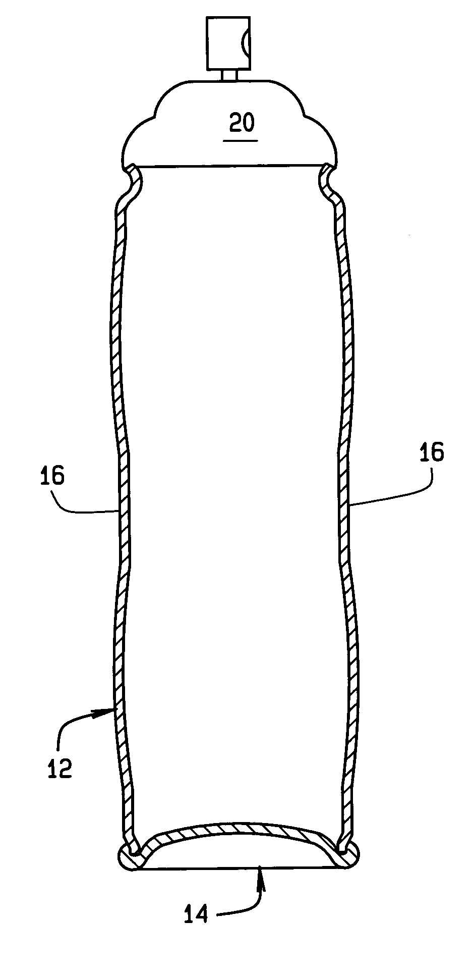
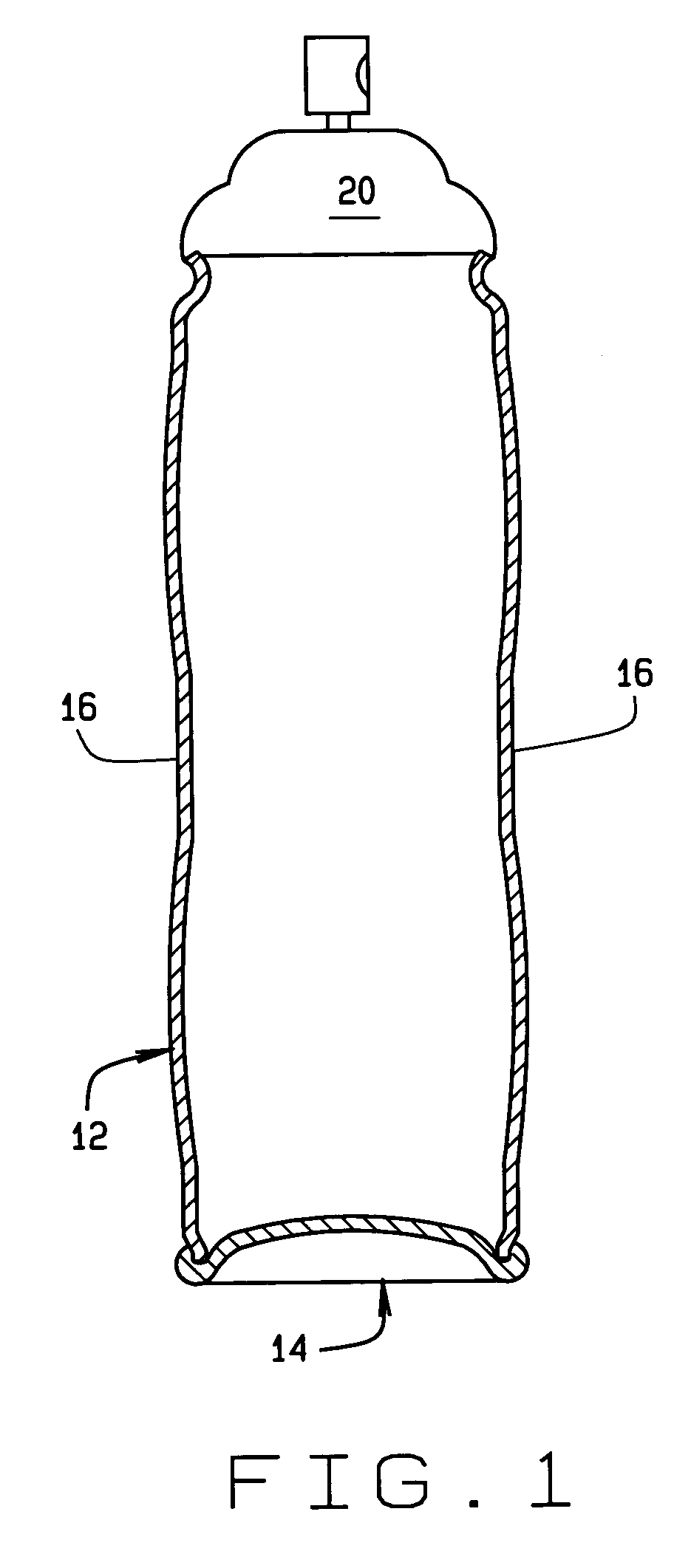
[0016] Referring to the drawings, a container such as aerosol dispensing container is indicated generally 10. The container comprises a body 12 initially formed from a blank, as is well-known in the art, and a dome shaped base 14 to which the lower end of the can body is crimped, again as is well-known in the art. Container ...


PUM

PropertyMeasurementUnit
Forceaaaaaaaaaa
Lengthaaaaaaaaaa
Shapeaaaaaaaaaa

Abstract

A method for shaping an aerosol container (10) to a desired body contour. A container body (12) is formed into a cylindrical shape and installed into a mold (30) whose inner surface defines the desired body contour. A bladder (74) is fitted onto a tool (50) insertable into an open end (M) of the container body. Once the tool is inserted, the bladder is inflated with a hydraulic fluid. Pressurizing the bladder forces the bladder against a sidewall of the body forcing the body outwardly and deforming it against the inside of the mold. After the container body is shaped, the bladder is de-pressurized and the tool withdrawn leaving the container with a defined body contour. The hydraulic fluid with which the bladder is pressurized is, at all times, contained within the bladder and does not contact the container sidewall so no subsequent drying of the container is required after the shaping process is complete.

Description

CROSS REFERENCE TO RELATED APPLICATIONS [0001] None STATEMENT REGARDING FEDERALLY SPONSORED RESEARCH OR DEVELOPMENT [0002] N / A BACKGROUND OF THE INVENTION [0003] This invention relates to shaped metal containers and the like, and more particularly, to hydraulic shaping of such cans. [0004] Aerosol containers are used to store a fluid or fluent material under pressure and to release the material, as a spray, foam, or gel when a valve is activated. The containers are formed from flat sheets of material which are first cut into rectangular shapes. The resulting blanks are then formed into a cylinder which is open at one end. The container is then filled with the material to be dispensed by the container. A valve assembly is attached to the upper, open end of the container. The contents of the container are subsequently released through a dispensing valve operable by the user of the container. [0005] Current manufacturing processes for aerosol containers have certain drawbacks. A major ...

Claims


Application Information

Patent Timeline
IPC IPC(8): G01F11/00B67B7/00
CPCB21D22/125B21D26/049Y10T29/49805B65D83/38B21D51/2646
Inventor KUBACKI, EDWARD F.CZAMOTA, JOHN
Owner BALL METALPACK LLC
Why Eureka
Try Eureka