
Spark plug

Active Publication Date: 2006-03-23
NGK SPARK PLUG CO LTD
View PDF9 Cites 7 Cited by
  • Summary
  • Abstract
  • Description
  • Claims
  • Application Information

AI Technical Summary

Benefits of technology

[0009] According to a result of the present inventors' examination, there is obtained a finding that the sweating and peeling of the discharge portion can be suppressed when the discharge portion is made of a precious metal tip containing Ir as a main component, Rh, and Ni and further containing at least one of Pt and Pd. Accordingly, when the discharge portion is made of precious metal tip containing Ir as a main component, Rh and Ni and further containing at least one of Pt and Pd, the sweating and peeling of precious metal in a surface of the discharge portion can be suppressed while the sparking abrasion, oxidation abrasion and abnormal abrasion up to now can be suppressed. Incidentally, in the invention, the phrase “Ir as a main component” means that 50 wt % or more of Ir is contained in the precious metal tip.
[0021] Preferably, the ground electrode-side precious metal tip may be characterized in that it contains 5.2 mass % to 41 mass % of Ru. As a result, it is possible to suppress occurrence of peeling of the ground electrode-side discharge portion and suppress abrasion and deformation of the ground electrode-side discharge portion. It is further preferable that the ground electrode-side precious metal tip contains 8 mass % to 20 mass % of Ru.

Problems solved by technology

If the peeling occurred, the volume of the discharge portion decreased to thereby spoil durability.
Incidentally, the peeling could not be eliminated perfectly by the background-art method provided to suppress the spark abrasion, oxidation abrasion and abnormal abrasion of the discharge portion.

Method used


Image

  • Spark plug
  • Spark plug
  • Spark plug

Examples


embodiment 1

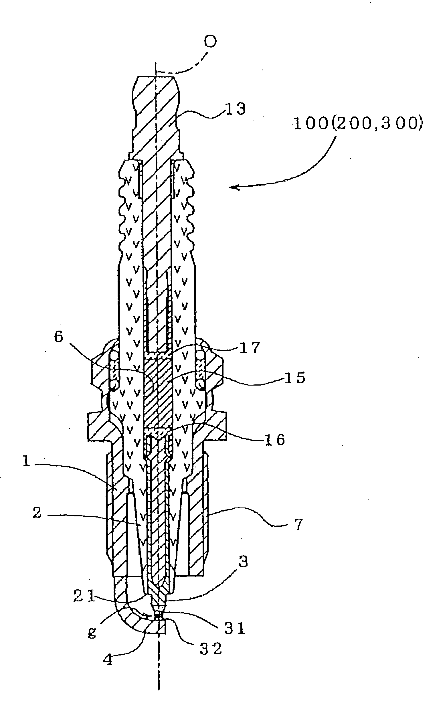
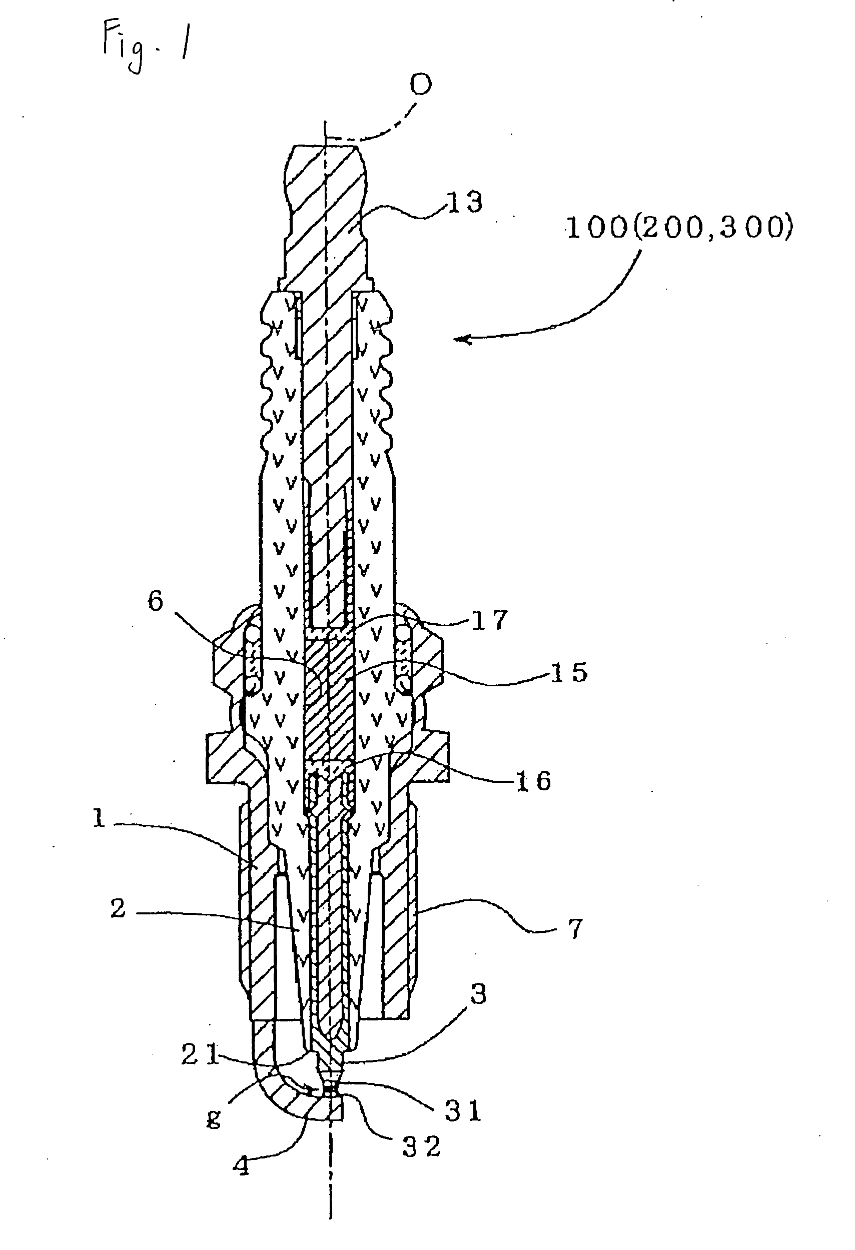
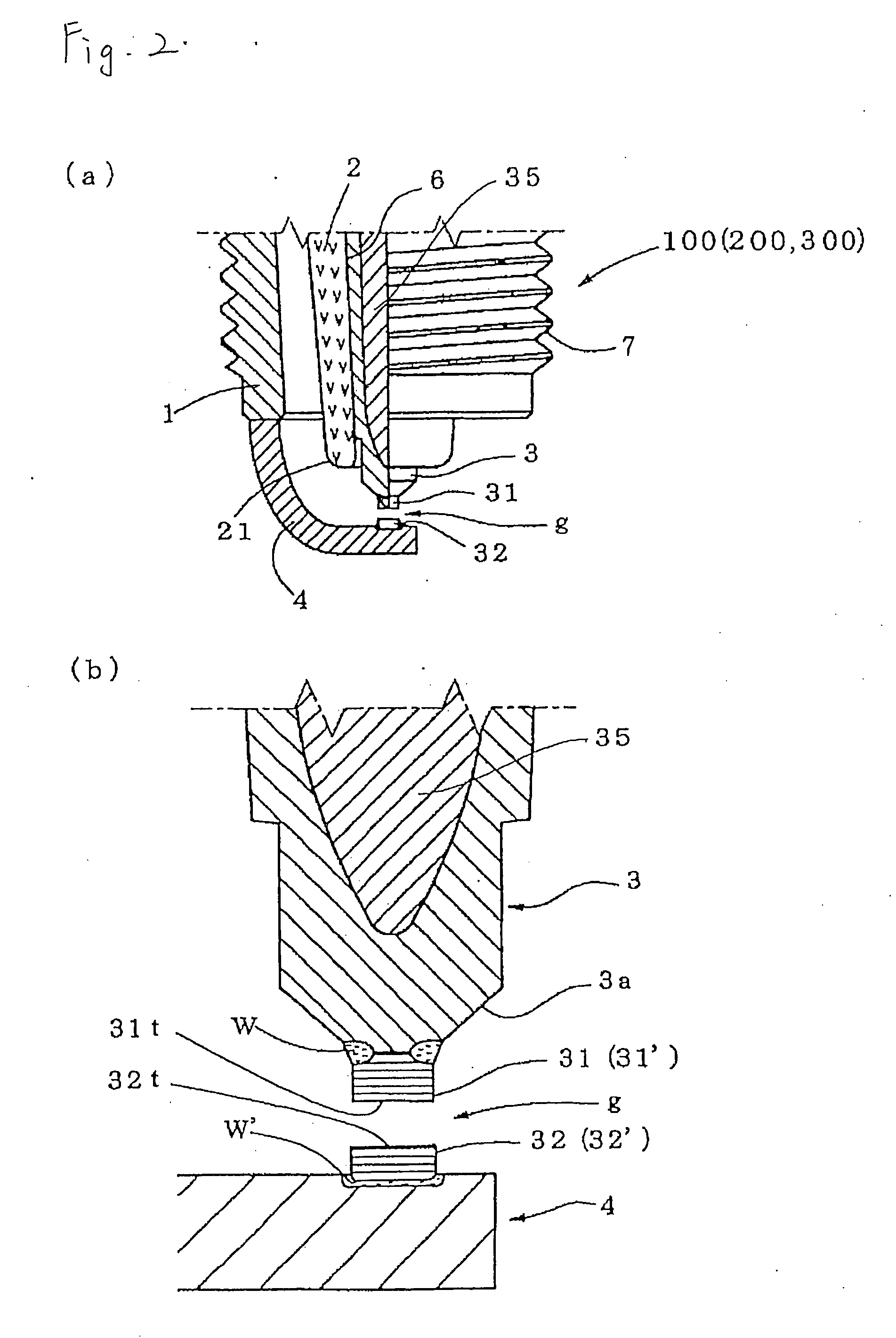
[0026] An embodiment of the invention will be described below on the basis of sectional view. FIG. 1 is a longitudinal sectional view showing an example of a spark plug 100 according to the invention. FIG. 2(a) is an enlarged view of a discharge portion of the spark plug 100 and its neighbor. The resistor-including spark plug 100 taken as an example of the invention includes a cylindrical metal shell 1, an insulator 2, a center electrode 3, a ground electrode 4, and so on. The insulator 2 is fitted into the metal shell 1 so that a leading end portion 21 of the insulator 2 protrudes out from the metal shell 1. The center electrode 3 is provided inside the insulator 2 in the condition that a center electrode-side discharge portion 31 formed at a leading end of the center electrode 3 is protruded out from the insulator 2. The ground electrode 4 has one end jointed to the metal shell 1 by means of welding or the like, and the other end bent toward one side so that the other end side sur...

embodiment 2

[0036] Embodiment 2 of the invention will be described below.

[0037] Incidentally, main differences of a spark plug 200 according to Embodiment 2 from the spark plug 100 according to Embodiment 1 are a center electrode-side precious metal tip 31′ forming a center electrode discharge portion 31 and a ground electrode-side precious metal tip 32′ forming a ground electrode-side discharge portion 32. Other parts of the spark plug 200 are almost the same as those of the spark plug 100. Accordingly, the parts different from those in Embodiment 1 will be mainly described while description about the parts the same as those in Embodiment 1 will be omitted or simplified.

[0038] For example, as shown in FIG. 2, the center electrode-side discharge portion 31 is formed in such a manner that a disc-like center electrode-side precious metal tip 31′ is superposed on the end surface of a leading end portion 3a of a center electrode 3 and fixed by a welding portion W formed by means of laser welding ...

embodiment 3

[0041] Embodiment 3 of the invention will be described below.

[0042] Incidentally, main differences of a spark plug 300 according to Embodiment 3 from the spark plug 100 according to Embodiment 1 and the spark plug 200 according to Embodiment 2 are a center electrode-side precious metal tip 31′ forming a center electrode discharge portion 31 and a ground electrode-side precious metal tip 32′ forming a ground electrode-side discharge portion 32. Other parts of the spark plug 300 are almost the same as those of the spark plug 100 or 200. Accordingly, the parts different from those in Embodiments 1 and 2 will be mainly described while description about the parts the same as those in Embodiments 1 and 2 will be omitted or simplified.

[0043] For example, as shown in FIG. 2, the center electrode-side discharge portion 31 is formed in such a manner that a disc-like center electrode-side precious metal tip 31′ is superposed on the end surface of a leading end portion 3a of a center electrod...


PUM

PropertyMeasurementUnit
Percent by massaaaaaaaaaa

Abstract

An object of the invention is to provide a spark plug having a discharge portion made of a precious metal tip, in which peeling of the precious metal tip from a surface of the discharge portion can be suppressed while spark abrasion, oxidation abrasion and abnormal abrasion of the discharge portion can be suppressed. The invention comprises a center electrode (3), and a ground electrode (4) disposed so that its side surface is opposite to a leading end portion of the center electrode (3), characterized in that: a center electrode-side precious metal tip (31′) or a ground electrode-side precious metal tip (32′) is welded to at least one of the center electrode (3) and the ground electrode (4) to thereby form a center electrode-side discharge portion (31) having a center electrode-side discharge-surface (31t) or a ground electrode-side discharge portion (32) having a ground electrode-side discharge surface (32t) in a position opposite to a spark discharge gap g; and the center electrode-side precious metal tip (31′) or the ground electrode-side precious metal tip (32′) contains Ir as a main component, Rh, and Ni and further contains at least one of Pt and Pd.

Description

TECHNICAL FIELD [0001] The present invention relates to a spark plug used in an internal combustion engine. BACKGROUND [0002] A spark plug used for ignition in an internal combustion engine such as an automobile engine has a tendency toward increase in temperature inside a combustion chamber for the purposes of increase in engine output and improvement in fuel efficiency. An engine of the type having a combustion chamber into which a discharge portion of a spark plug is protruded while located opposite to a spark discharge gap of the spark plug has been used widely in order to enhance ignitability. Under such circumstances, the discharge portion of the spark plug is apt to be worn out acceleratedly by spark discharge because it is exposed to a high temperature. In order to improve spark resistance of the discharge portion opposite to the spark discharge gap, a large number of proposals have been made for a spark plug of the type in which a precious metal tip mainly containing Ir or ...

Claims


Application Information

Patent Timeline
IPC IPC(8): H01T13/20H01T13/39
CPCC22C1/0466H01T13/39C22C32/0021C22C5/04
Inventor YOSHIMOTO, OSAMUMATSUTANI, WATARUMATSUBARA, YOSHIHIRONUNOME, KENJI
Owner NGK SPARK PLUG CO LTD
Learn More