Gate driving unit and display device having the same

Active Publication Date: 2006-03-23
SAMSUNG DISPLAY CO LTD
View PDF7 Cites 51 Cited by
  • Summary
  • Abstract
  • Description
  • Claims
  • Application Information

AI Technical Summary

Benefits of technology

[0009] The present invention provides a gate driving unit capable of preventing mal

Problems solved by technology

This configuration causes parasitic capacitances between the connecting wirings CL and the vertical synchronization start signal wiring STVL, the clock wiring CKVL, the clock-bar wiring CKVBL, and the off voltage wiring Vof

Method used


Image

  • Gate driving unit and display device having the same
  • Gate driving unit and display device having the same
  • Gate driving unit and display device having the same

Examples


Embodiment Construction

[0023] Hereinafter the embodiments of the present invention will be described in detail with reference to the accompanied drawings.

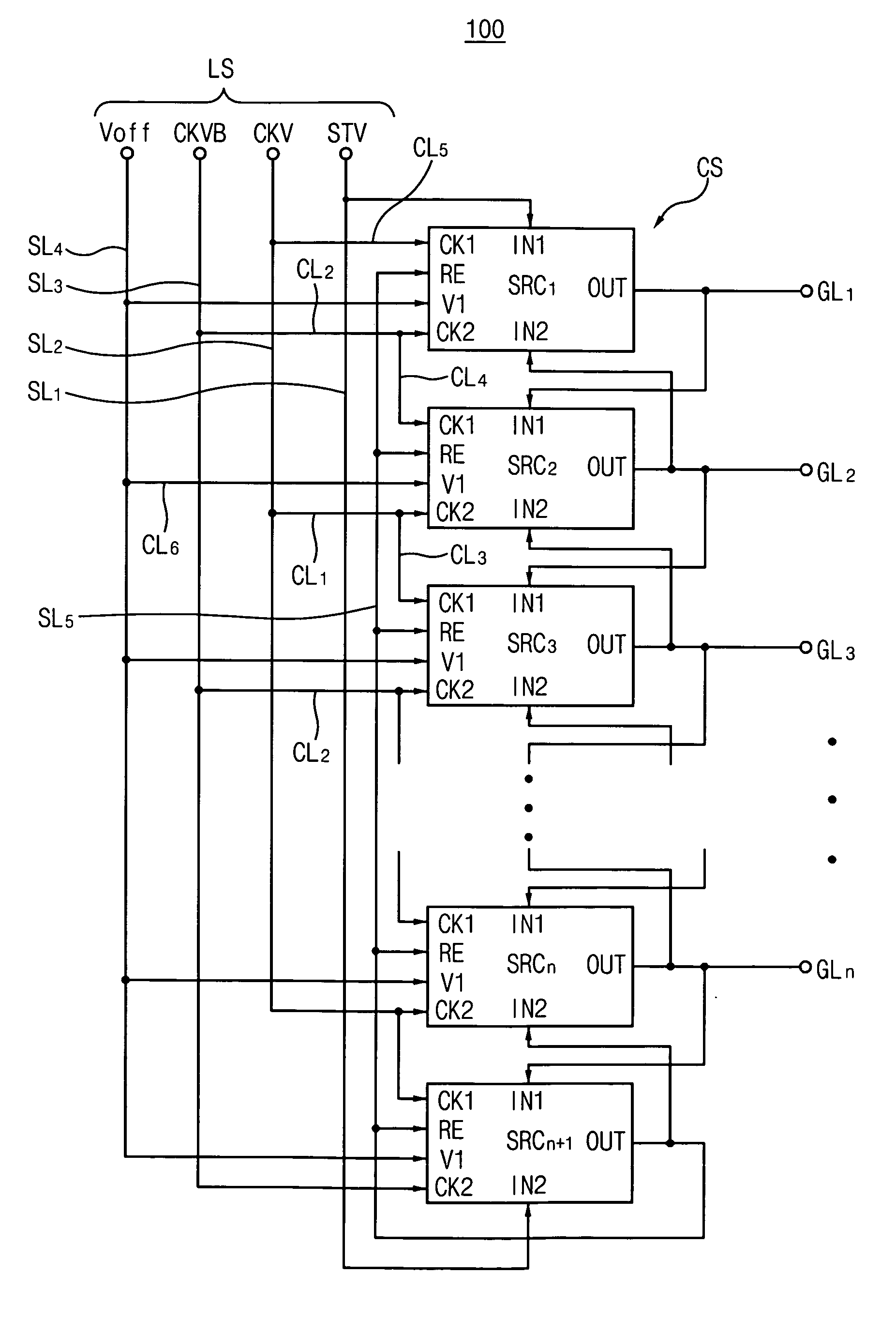
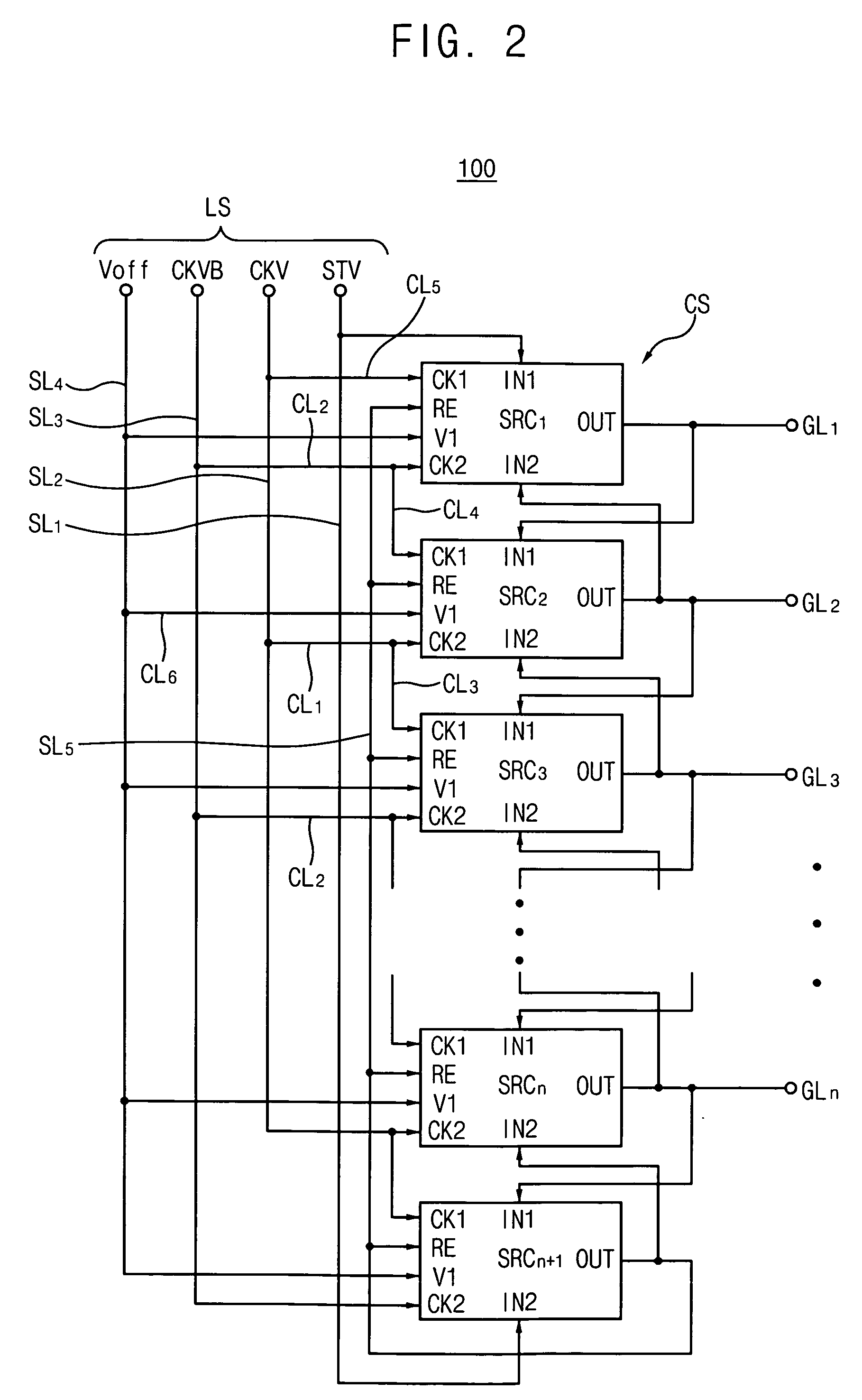
[0024]FIG. 2 is a block diagram of a gate driver 100 according to an exemplary embodiment. Referring to FIG. 2, the gate driver 100 includes a circuit portion CS outputting gate output signals and a wiring portion LS delivering gate control signals to the circuit portion CS.

[0025] The circuit portion CS includes first, second, . . . , (n+1)th stages SRC1, SRC2, . . . , SRC(n+1) (wherein, n is an even number). The first, second, . . . , (n+1)th stages SRC1, SRC2, . . . , SRC(n+1) include a first clock terminal CK1, a second clock terminal CK2, a first input terminal IN1, a second input terminal IN2, a voltage terminal V1, a reset terminal RE, and an output terminal OUT. The first clock terminal CK1 of each of the odd-numbered stages SRC1, SRC3, . . . , SRC(n+1) is operatively coupled to a first clock CKV, and the first clock terminal CK1 of each of the ...


PUM


Abstract

A gate driver includes multiple stages. Each stage has a circuit portion and a wiring portion. The wiring portion delivers first and second clock signals to the circuit portion. Further, the wiring portion includes first and second clock wirings receiving the first and second clock signal, respectively, first connecting wirings electrically connecting the first clock wiring with a first every other stage, and second connecting wirings electrically connecting the second clock wiring with the odd-numbered stages. Further, the wiring portion includes third connecting wirings electrically connecting the first connecting wiring with a second every other stage and fourth connecting wirings electrically connecting the second connecting wiring with the even-numbered stages. This configuration may prevent the gate driver from operating erroneously and reduce power consumed by the gate driver.

Description

BACKGROUND OF THE INVENTION [0001] 1. Field of the Invention [0002] The present invention relates to a gate driving unit and a display device having the same, and more particularly, to a gate driving unit having a reduced number of contact electrodes, and a display device having the same, thereby preventing malfunction thereof. [0003] 2. Description of the Related Art [0004] Generally, a display device includes a display panel, gate drivers outputting gate signals for driving the display panel, and data drivers outputting data signals to the display panel. The gate and data drivers are integrated circuits, for example, and are affixed to the display panel. However, there is a recent tendency that the gate drivers are formed on the display panel for reducing failure of the display device while affixing the gate driver to the display panel. [0005]FIG. 1 is a layout diagram of a conventional gate driver formed on the display panel. As shown in FIG. 1, the gate driver 10 includes a wiri...

Claims


Application Information

Patent Timeline
IPC IPC(8): G09G5/00
CPCG09G3/3677G11C19/184G09G2300/0426G02F1/133G09G3/36
Inventor PARK, HAENG-WONMOON, SEUNG-HWANKANG, NAM-SOOMOON, SUNG-JAEKIM, SUNG-MANLEE, SEONG-YOUNGLEE, YONG-SOON
Owner SAMSUNG DISPLAY CO LTD
Why Eureka
Try Eureka