
Joint component framework for modeling complex joint behavior

a joint component and complex technology, applied in the field of joint modeling, can solve the problems of increasing the complexity of the user's manipulation or use of the resulting joint expression, limiting the choice of parameterization for particular orientations, and physiological joints have been shown to have many complexes, so as to achieve the effect of sufficient compactness and increasing the accuracy of the joint model

Active Publication Date: 2006-03-23
HONDA MOTOR CO LTD
View PDF29 Cites 41 Cited by
  • Summary
  • Abstract
  • Description
  • Claims
  • Application Information

AI Technical Summary

Benefits of technology

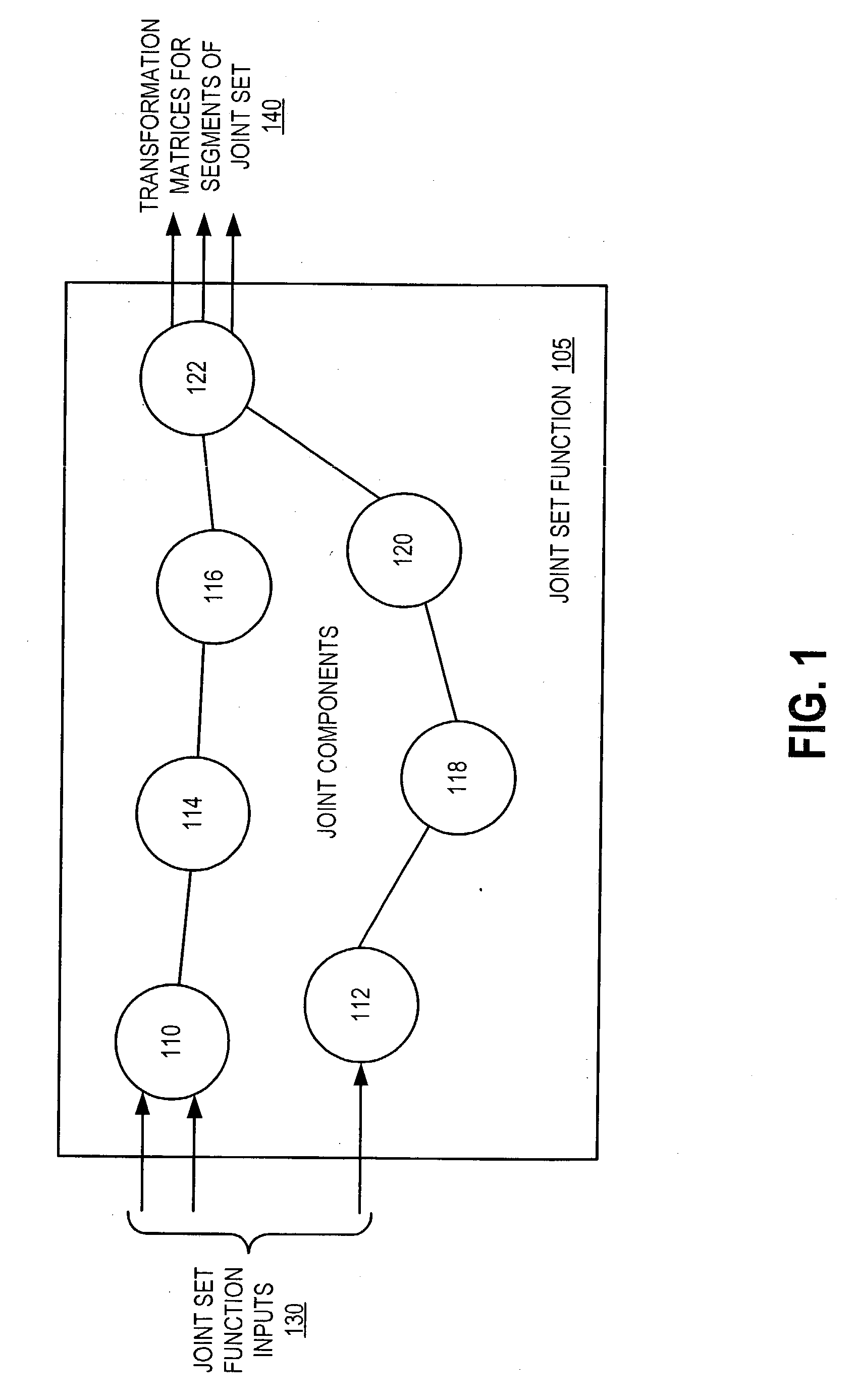
[0013] In another embodiment of the present invention, the inputs to the joint set function can be designed to have intuitive interpretations to a user such as an animator, and be sufficiently compact because the dependencies and the coupling of the joints are implicitly built into the joint set function. Joint components can be reused in different contexts or extended to incorporate increasing accuracy in the joint model.

Problems solved by technology

Multiple sets of parameters can be combined to achieve multiple degree of freedom (DOF) joints, but additional complexity is added for the user to manipulate or to make use of the resulting joint expressions.
One disadvantage of Euler angles, however, is that the choice of parameterization is restricted for particular orientations.
Physiological joints have been shown to have many complexities that are often neglected in graphical models.
Techniques that use specialized models to represent biomechanical or physiological complexity can be difficult for users to configure and to control.
Further, the majority of commercial software that provides visualization features for three-dimensional (3-D) modeling does not support the complexity of multiple DOF joints or specialized models.
Other conventional approaches lack the generality needed to include changing joint centers, surface constraints, and joint sinus cones for joint limits on ball-and-socket joints.
One problem with conventional systems that provide a high level organization to coordinate individual joints is that they are not sufficiently generalized to represent all joints accurately.
Another problem with conventional systems is that joint models are not easily exchanged or interchanged among software environments.
Although a standard human representation is important for avatar exchange and compatibility in different software, the flexibility to define new coordinated articulations is hampered by constraints enforced by the hierarchy.

Method used


Image

  • Joint component framework for modeling complex joint behavior
  • Joint component framework for modeling complex joint behavior
  • Joint component framework for modeling complex joint behavior

Examples


Embodiment Construction

[0029] The present invention is now described more fully with reference to the accompanying figures, in which several embodiments of the invention are shown. The present invention may be embodied in many different forms and should not be construed as limited to the embodiments set forth herein. Rather these embodiments are provided so that this disclosure will be thorough and complete and will fully convey the invention to those skilled in the art.

[0030] In computer graphics applications, realistic depiction and animation of human characters is an important element contributing to the appeal and success of interactive graphics. Three-dimensional humanoids are often the physical embodiment of the interactive interface, either serving as an avatar for the player, or as representations of other autonomous characters in the virtual environment. While recent research has focused on better geometric representations, anatomy-based modeling, and pose-based skin deformation for representing...


PUM


Abstract

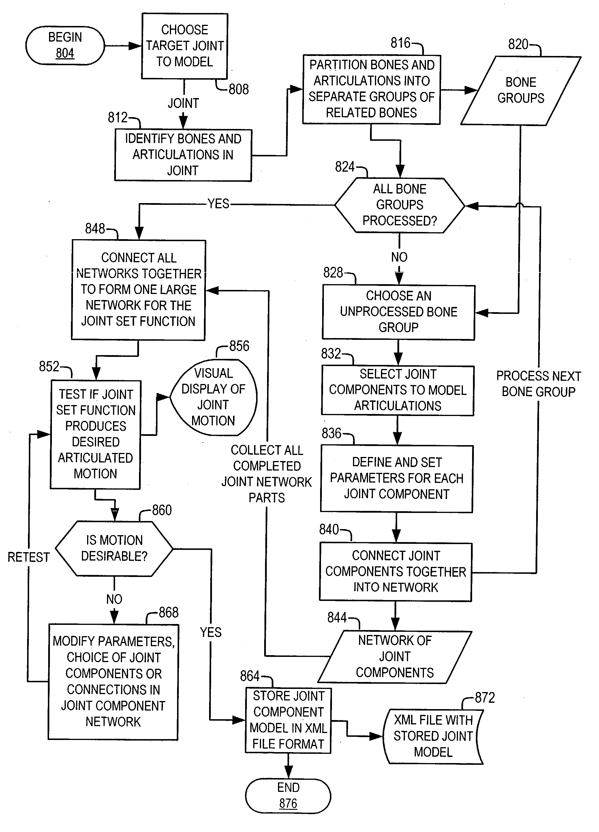
A general joint component framework that is capable of exhibiting complex behaviors of joints in articulated figures is provided. A network of joint components is used to model the kinematics of a joint. A joint builder can specify parameters for each of the joint components and join the joint components to form a joint set function that captures the biomechanical dependencies between the components. The joint function has fewer inputs than the total number of possible articulations yielding both simple control and biomechanically accurate joint movement.

Description

TECHNICAL FIELD [0001] This invention relates generally to joint modeling, and more particularly, to a component framework that offers complex articulation and biomechanical accuracy for representing joints. BACKGROUND [0002] Accurate representation of skeletal articulations is important for many applications including biomechanics and computer graphics. In biomechanics, for example, accurate joint models can be used for injury prevention and rehabilitation. For computer graphics, accurate joint models can lead to improved realism in character animation. [0003] One conventional approach for representing human characters with an articulated joint model uses the Denavit-Hartenberg link parameter notation from robotics to represent figures with articulated limbs. One such conventional system is described in M. Girard et al., “Computational modeling for the computer animation of legged figures,” Computer Graphics (SIGGRAPH '85 Proceedings), vol. 19, pp. 263-270, 1985, which is incorpora...

Claims


Application Information

Patent Timeline
Patent Type & Authority Applications(United States)
IPC IPC(8): G06T15/70G06T13/00G06T17/40
CPCG06T13/40G06T2213/04G06T2210/41G06T19/00
Inventor NG-THOW-HING, VICTORSHAO, WEI
Owner HONDA MOTOR CO LTD
Learn More