Increased yield of cubic crystalline optical elements by crystal orientation

a technology of optical elements and cubic crystalline elements, applied in the field of cubic crystalline optical elements, can solve the problems of limited number of materials capable of transmitting ultraviolet light, insufficient transmissivity of ordinary optical materials, and weakening of material limitations that do transmit ultraviolet light,

Active Publication Date: 2006-03-23
CORNING INC
View PDF1 Cites 4 Cited by
  • Summary
  • Abstract
  • Description
  • Claims
  • Application Information

AI Technical Summary

Benefits of technology

[0015]FIG. 1 illustrates a seven step method, designated as steps A-G, for i

Problems solved by technology

The short-wavelength high-photon-energy content of deep ultraviolet (UV) light (wavelengths between approximately 120 nanometers and 250 nanometers) significantly limits the number of materials capable of transmitting ultraviolet light and amplifies weaknesses in the limited number of materials that do tran

Method used


Image

  • Increased yield of cubic crystalline optical elements by crystal orientation
  • Increased yield of cubic crystalline optical elements by crystal orientation
  • Increased yield of cubic crystalline optical elements by crystal orientation

Examples


Embodiment Construction

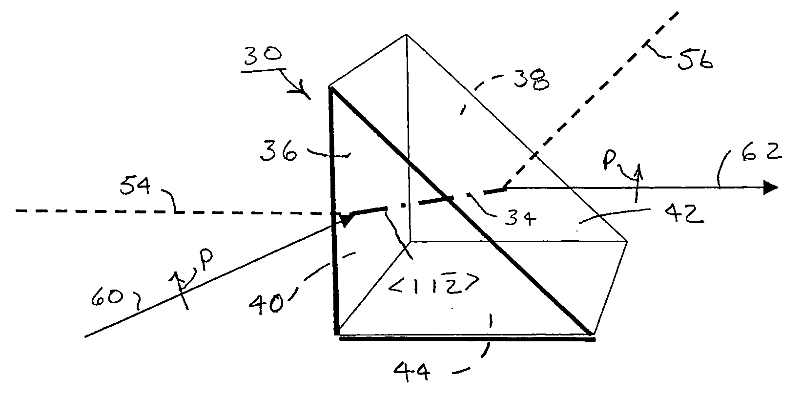
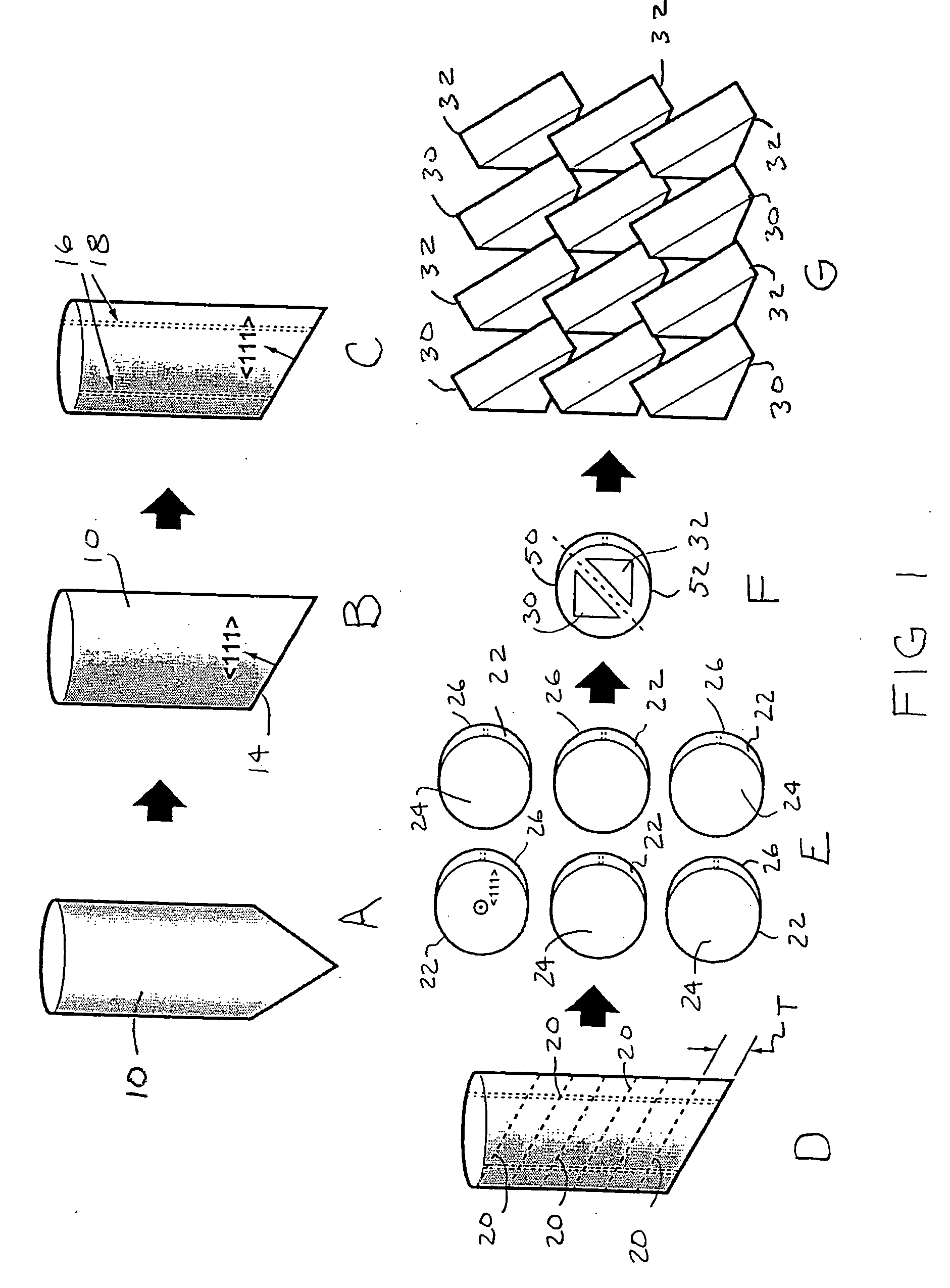
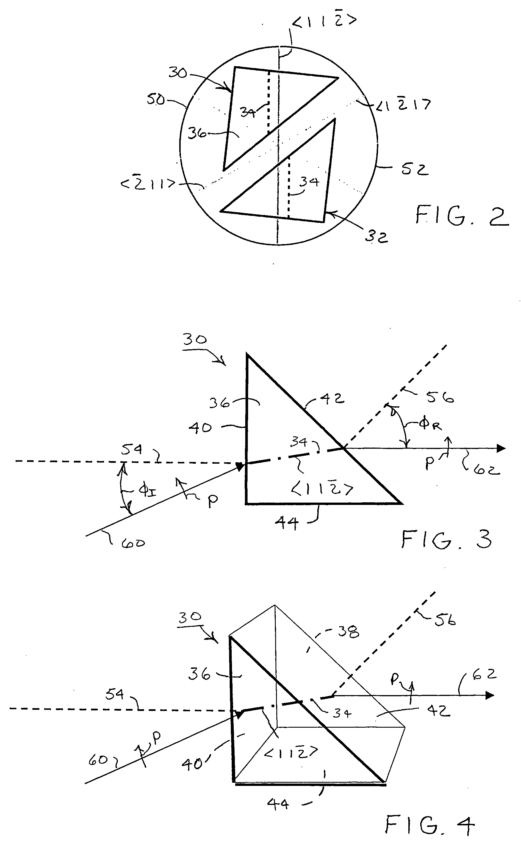
[0019] A sequence of processing steps laid out in FIG. 1 exemplifies a method for increasing yield of optical elements from a cubic crystal material in accordance with the invention. Beginning with Step A, a crystal rod 10 made of calcium fluoride is grown either with randomly oriented crystal axes or with crystal axes having a preferred orientation imposed by seeding. Either way, the exact orientation of the crystal axes is not immediately apparent from the crystal rod.

[0020] In Step B, the crystal rod 10 is cleaved near one end along the {1 1 1} plane normal to the main axis. In such calcium fluoride crystals, this is the crystal plane along which the crystal most readily breaks and provides a convenient and accurate reference plane 14 for the crystal rod 10. Although the {1 1 1} reference plane 14 identifies one of the crystal axes, i.e., the main crystal axis, it is necessary to identify a second axis to fully orient the cubic crystal.

[0021] Step C involves an inspection pro...


PUM


Abstract

Increased yield of optical elements from cubic crystal rods, such as made of calcium fluoride, is made possible by orienting the optical elements for supporting the propagation of light along one of the <1 1 {overscore (2)}>, <1 2 1>, or <{overscore (2)} 1 1> alternative crystal axis, which extend perpendicular to a main <1 1 1> crystal axis. A cleave is taken through the crystal rod along a primary crystal plane {1 1 1} normal to the <1 1 1> main axis. One of the <1 1 {overscore (2)}>, <1 {overscore (2)} 1>, or <{overscore (2)} 1 1> alternative crystal axes is located by optical inspection and indicated on the crystal rod with an orientation label. Additional cuts are taken parallel to the {1 1 1} primary crystal plane to divide the crystal rod into disks each containing a portion of the orientation label. The disks can be cut again and sides formed perpendicular to the {1 1 1} primary crystal plane with regard to the orientation labels for forming optical elements, such as prisms, oriented for supporting the propagation of polarized light along one of the <1 1 {overscore (2)}>, <1 {overscore (2)} 1>, and <{overscore (2)} 1 1 > alternative crystal axes.

Description

BACKGROUND OF THE INVENTION [0001] 1. Field of the Invention [0002] The invention relates to cubic crystalline optical elements, particularly calcium fluoride, in forms such as prisms for propagating highly collimated, linearly polarized light along predetermined crystal axes and to the manufacture and use of such cubic crystalline optical elements. [0003] 2. Description of Related Art [0004] The short-wavelength high-photon-energy content of deep ultraviolet (UV) light (wavelengths between approximately 120 nanometers and 250 nanometers) significantly limits the number of materials capable of transmitting ultraviolet light and amplifies weaknesses in the limited number of materials that do transmit such ultraviolet light. Most ordinary optical materials are either insufficiently transmissive or subject to breakdown by absorption. [0005] Calcium fluoride (CaF2) is among the optical materials capable of transmitting deep UV light. Despite calcium fluoride's highly symmetric cubic cry...

Claims


Application Information

Patent Timeline
IPC IPC(8): G02F1/1335
CPCG02B27/283G02B1/02
Inventor ARONSTEIN, DAVID L.GOODMAN, DOUGLAS S.THEN, PAUL M.
Owner CORNING INC
Why Eureka
Try Eureka