Electric variable transmission with de-coupled engine charging in reverse

a technology of electric variable transmission and reverse charging, which is applied in the direction of electric propulsion mounting, transportation and packaging, and small apus and even large energy storage devices cannot meet the needs of high-average power vehicles or address duty cycles that require continuous, constant speed operation, and steep grades. , to achieve the effect of reducing the size of the second motor/generator, reducing the packaging envelope, and reducing cost and mass

Inactive Publication Date: 2006-03-23
GM GLOBAL TECH OPERATIONS LLC
View PDF7 Cites 43 Cited by
  • Summary
  • Abstract
  • Description
  • Claims
  • Application Information

AI Technical Summary

Benefits of technology

[0029] The fifth torque-transmitting mechanism selectively disconnects the second planetary gear set from the third planetary gear set so that the second motor/generator may drive the output member while disconnected from the first motor/generator and the engine. The engine assists by driving the first motor/generator, which acts as a generator, to charge the battery, which transfers energy

Problems solved by technology

However, such combinations of small APUs and even large energy storage devices do not accommodate high-average power vehicles or address duty cycles that demand continuous, constant speed operation.
Steep grades and sustained high-average cruising speeds at desired high efficiencies are not achievable with a typical, series, hybrid transmission configuration.
The challenge, therefore, is to provide a power system that will operate at high efficiencies over a wide variety of operating conditions.
However, when the two gear members rotate in the same direction, but at different speeds, the direction in which the third gear member rotat

Method used


Image

  • Electric variable transmission with de-coupled engine charging in reverse
  • Electric variable transmission with de-coupled engine charging in reverse
  • Electric variable transmission with de-coupled engine charging in reverse

Examples


Embodiment Construction

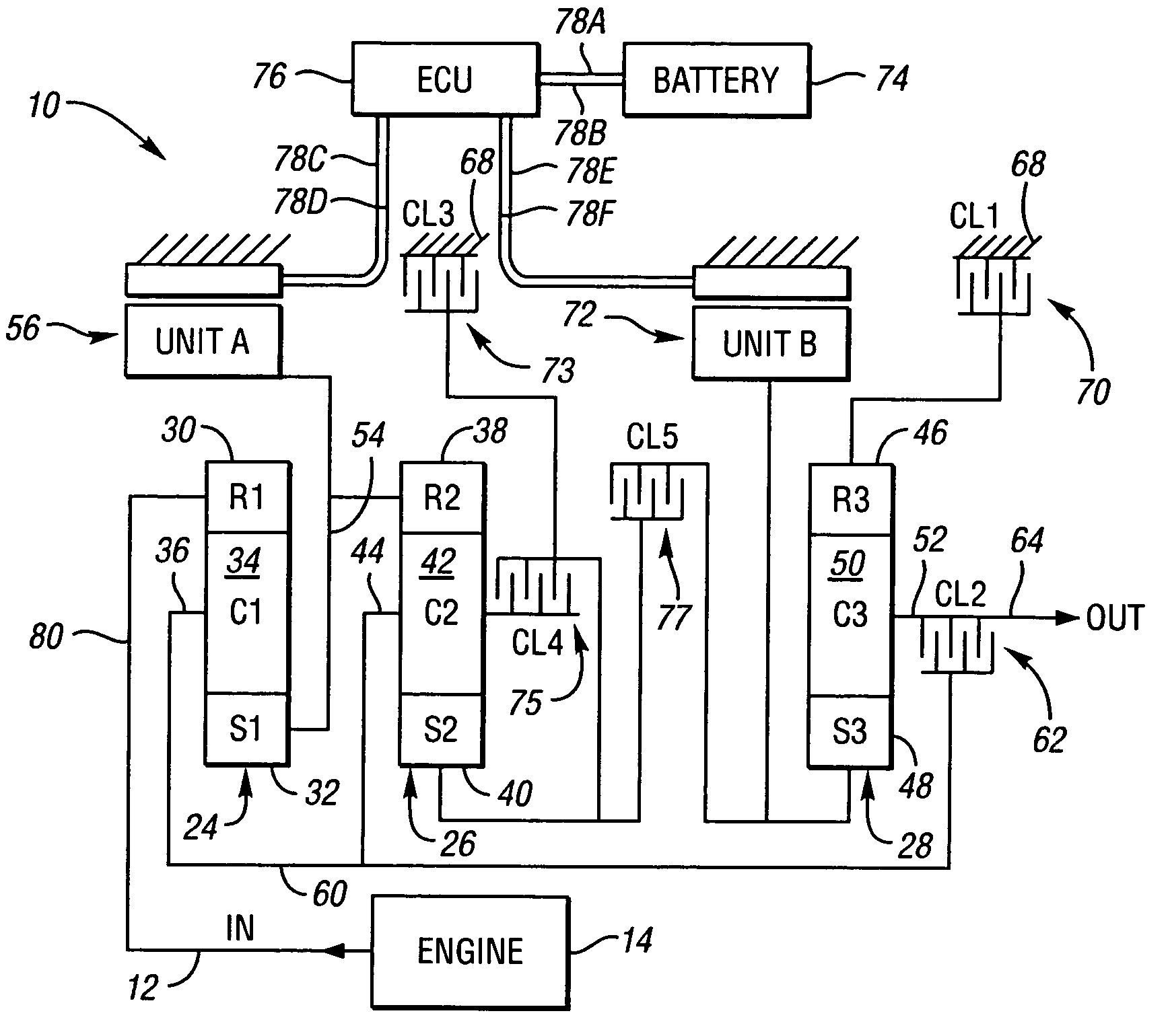
[0034] One representative form of a two-mode, compound-split, electromechanical transmission embodying the concepts of the present invention is depicted in FIG. 1, and is designated generally by the numeral 10. The hybrid transmission 10 has an input member 12 that may be in the nature of a shaft which may be directly driven by an engine 14. A transient torque damper may be incorporated between the engine 14 and the input member 12 of the hybrid transmission 10. An example of a transient torque damper of the type recommended for the present usage is disclosed in detail in U.S. Pat. No. 5,009,301, which issued on Apr. 23, 1991 to General Motors Corporation and is hereby incorporated by reference in its entirety. The transient torque damper may incorporate, or be employed in conjunction with, a torque transfer device to permit selective engagement of the engine 14 with the hybrid transmission 10, but it must be understood that the torque transfer device is not utilized to change, or c...


PUM


Abstract

A hybrid electromechanical transmission includes first, second and third planetary gear sets, an input member, an output member, and first and second motor generators. At least one of the gear members in the first planetary gear set is connected to the first motor/generator. At least one of the gear members in the third planetary gear set is connected to the second motor/generator. First and second interconnecting members continuously connect members of the first planetary gear set with members of the second planetary gear set. Five torque-transmitting mechanisms selectively interconnect members of the planetary gear sets with a stationary member or with other members of the planetary gear sets. One of the five torque-transmitting mechanisms is operative to selectively disconnect the second planetary gear set from the third planetary gear set so that the second motor/generator may drive the output member while disconnected from the first motor/generator and the input member.

Description

TECHNICAL FIELD [0001] The present invention relates to a hybrid electromechanical vehicular transmission that utilizes three interactive planetary gear sets that are operatively connected to an engine and two motor / generators, and includes five clutches, wherein one clutch is operable to selectively de-couple the engine and one motor / generator from the other motor / generator. BACKGROUND OF THE INVENTION [0002] The purpose of a vehicular transmission is to provide a neutral, at least one reverse and one or more forward driving ranges that impart power from an engine, and / or other power sources, to the drive members which deliver the tractive effort from the vehicle to the terrain over which the vehicle is being driven. As such, the drive members may be front wheels, rear wheels or a track, as required to provide the desired performance. [0003] A series propulsion system is a system in which energy follows a path from an engine to an electric storage device and then to an electrical m...

Claims


Application Information

Patent Timeline
IPC IPC(8): F16H3/72
CPCB60K1/02B60K6/365B60K6/445Y02T10/6239F16H2037/102F16H2037/104F16H2200/201F16H3/728Y02T10/62
Inventor SOWUL, HENRYKHENDRICKSON, JAMES D.KLEMEN, DONALD
Owner GM GLOBAL TECH OPERATIONS LLC
Why Eureka
Try Eureka