Navigated drill guided resection block

a technology of guided resection and navigation drill, which is applied in the field of surgical devices, can solve the problems that finely adjusting the position of such devices even with the assistance of the computer system may still require substantial skill of the surgeon

Active Publication Date: 2006-03-23
HOWMEDICA OSTEONICS CORP
View PDF49 Cites 58 Cited by
  • Summary
  • Abstract
  • Description
  • Claims
  • Application Information

AI Technical Summary

Benefits of technology

[0015] A unique method for forming a planar surface on a bone involving several steps is permitted by providing such a two part cutting block operable for interfacing with a computer-aided navigation system. With the computer-aided navigation system, a first part of the two part cutting block with a planar cutting guide surface is approximately located in a proximal-distal direction on the bone near the necessary cutting position. Again using the computer-aided navigation system the rotational position of a second part of the cutting block is set about first and second axes generally perpendicular to the proximal-distal direction. After such positioning in this way, the second part of the block is pinned to the bone with a first pin. After such pinning to the bone, the user verifies and, if necessary, readjusts the rotational position of the cutting block about the first and second axes using the navigation system and then pins the second part of the block to the bone. This second pinning prevents rotation of the block about the first and second axes. Then, the practitioner verifies and, if necessary, readjusts the proximal-distal location of the first part using the navigation system by moving the first part in the proximal-distal direction with respect to the pinned second part. The planar bone surface may then be formed with the cutting guide on the first part of the cutting block.

Problems solved by technology

However, finely adjusting the position of such devices even with the assistance of the computer system may still require substantial skill of the surgeon due to the manual or free hand nature of the movement or re-positioning of the block and tracker.

Method used


Image

  • Navigated drill guided resection block
  • Navigated drill guided resection block
  • Navigated drill guided resection block

Examples


second embodiment

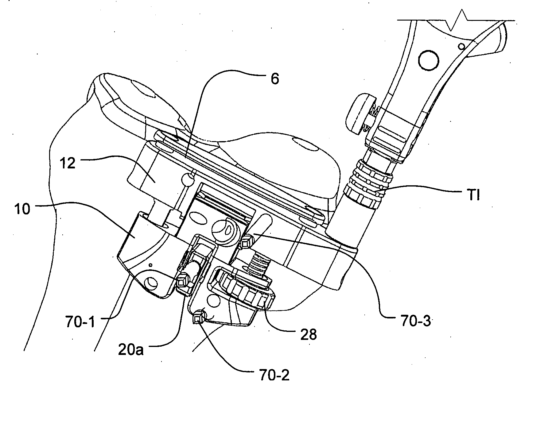
[0048] The components of the cutting block 2 of FIGS. 1 through 4 are illustrated in FIGS. 5 through 10. In this embodiment, axial translation along axis x by the guide extension 12 with respect to the main body 10 as previously described can be actuated by use of a traversing mechanism 28. In the illustrated example, the traversing mechanism 28 is a wheel or adjustment knob that has a threaded bore and is threaded onto a traversing post 14 having complementary threads 30. Rotation of the wheel-type traversing mechanism 28 in one direction traverses the guide extension 12 in one direction along the illustrated x axis. Changing the direction of the rotation of this wheel reverses the direction of the axial translation of the guide extension 12. In this way, controlled or regulated extension of the cutting guide is permitted.

[0049] In this embodiment, to prevent rotation of guide extension 12 with respect to main body 10, a second non-threaded post 15 is provided which slidingly engag...

first embodiment

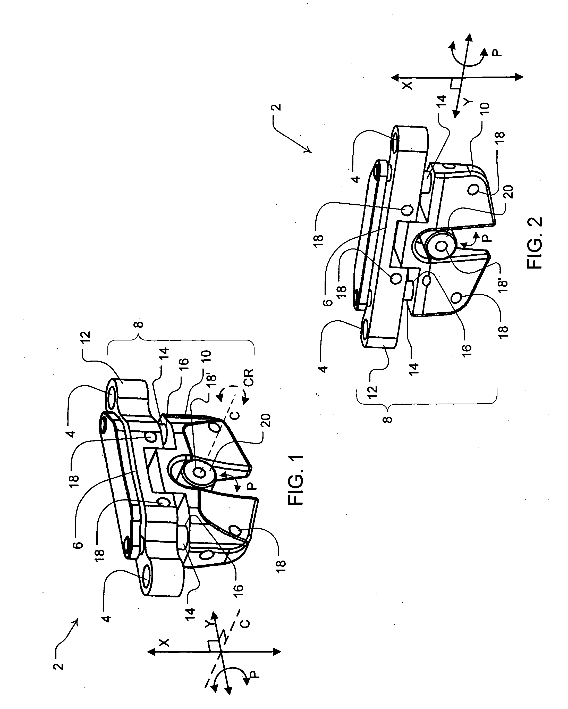
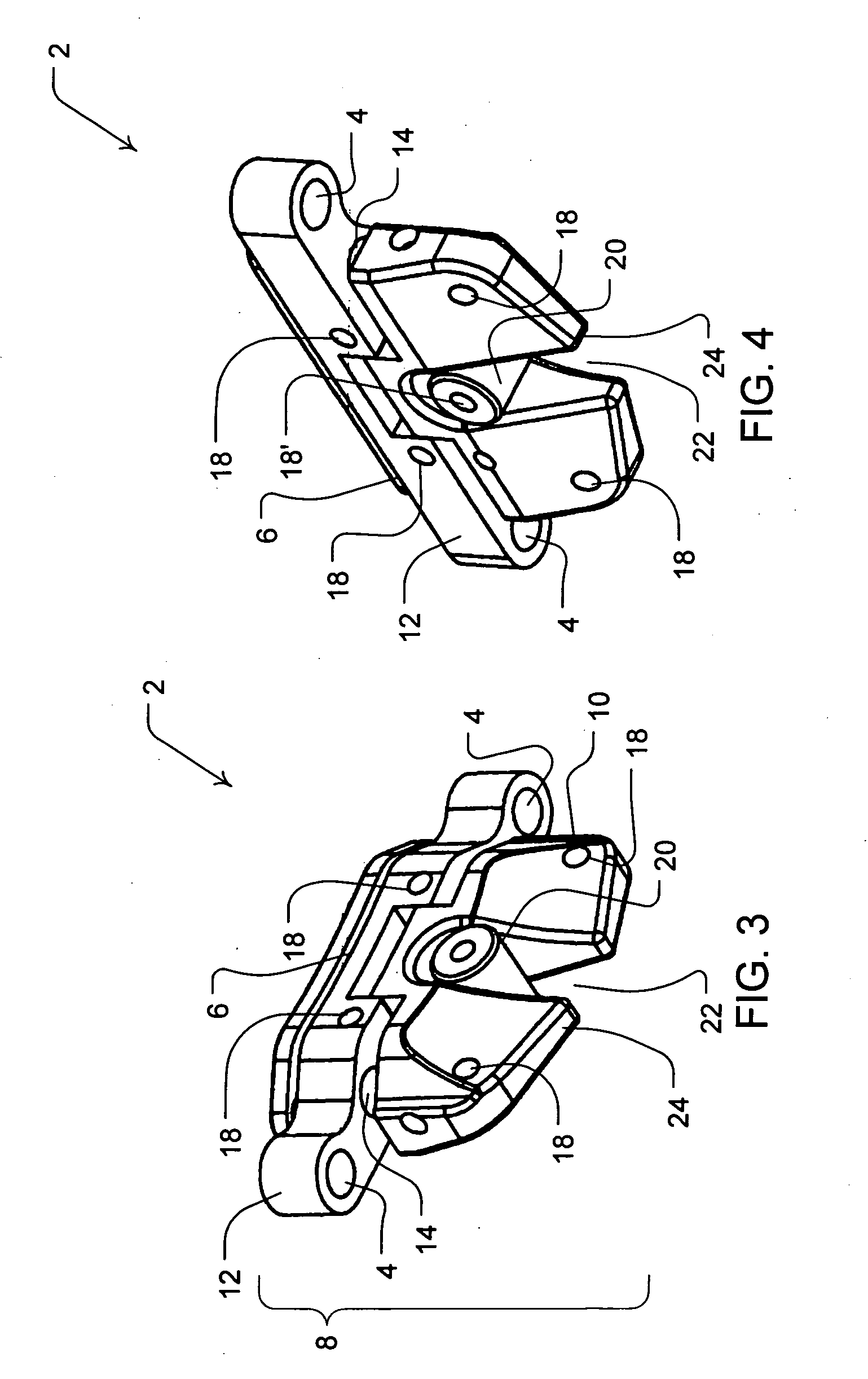
[0056] As with the first embodiment, this embodiment of the cutting block also has a universal design permitting either front or back faces to serve as either bone facing surface during a resection procedure. For example, the cutting guide 6, the swivel 20, pin holes 18, swivel pin hole 18′, handle mounting bore 42 and traversing mechanism 28 are all accessible for use from either face.

[0057] A third embodiment of the cutting block 2 is illustrated in FIGS. 11 through 14 and 15. In this embodiment, the swivel 20 may be the pin cylinder of the first embodiment previously described. Alternatively, as illustrated in FIGS. 11, 12 and 14, the swivel 20 is a swivel wheel 20a, which may optionally be implemented for tactile / regulated adjustment by one or more positioning actuators and / or a resistance actuator as previously described with respect to the second embodiment. Therefore, adjustment of the cutting block 2 of this embodiment for purposes of flexion / extension and varus / valgus using...


PUM


Abstract

A bone cutting guide block has a cutting tool guide surface and a navigation mount for a navigation tracker component for computer aided positioning of the guide for a resection procedure. In various embodiments, the guide includes a rotation means. Preferably, a swivel with a pivot apparatus is provided to limit rotation to permit controlled flexion-extension angle about the pivot with respect to the cutting guide surface. A fixing member through the swivel permits for varus-valgus adjustment of the guide surface. Optionally, a positioning actuator and/or biased resistance actuator implements more regulated flexion-extension angle adjustment with the swivel. Various traversing mechanisms, such as a threaded wheel or pivoted cam tool permit controlled proximal-distal adjustment of the cutting guide surface.

Description

FIELD OF THE INVENTION [0001] The present invention relates to surgical devices. More particularly, the invention involves a cutting block configured for navigated positioning with an automated tracker system and adjustment devices for precision alignment of the cutting block in response to information from the tracker system. BACKGROUND OF THE INVENTION [0002] Total knee arthroplasty involves replacement of portions of the patella, femur and tibia with artificial components. In particular, a proximal portion of the tibia and a distal portion of the femur are cut away (resected) and replaced with artificial components. In performing this knee surgery, it has been desirable to minimize the size of the incision to thereby minimize damage to soft tissue. [0003] In particular, it is necessary to resect the proximal tibia and distal femur with, among other cuts, a facing pair of planer cuts from which other bone cuts, in the case of the femur, can be referenced. [0004] In order to make t...

Claims


Application Information

Patent Timeline
Patent Type & Authority Applications(United States)
IPC IPC(8): A61F5/00
CPCA61B17/154A61B17/155A61B2017/0046A61B19/5244A61B17/157A61B34/20
Inventor RAISTRICK, JAMES W.BUEHLER, KNUTE C.COLLAZO, CARLOS E.
Owner HOWMEDICA OSTEONICS CORP
Why Eureka
Try Eureka