
Pilot acquisition and local clock calibration with reduced MIPS

a pilot acquisition and local clock technology, applied in the field of position location, can solve the problems of inability to achieve the level of positioning accuracy or reliability of the disclosed location technology, limited gps effect, and marginally useful signals

Inactive Publication Date: 2006-03-23
ROSUM CORP
View PDF4 Cites 61 Cited by
  • Summary
  • Abstract
  • Description
  • Claims
  • Application Information

AI Technical Summary

Problems solved by technology

However, the effectiveness of GPS is limited in some situations.
Thus the signal is marginally useful or not useful at all in the presence of line-of-sight blockage or while the receiver is inside a building.
However, the technique described the use of the horizontal and vertical synchronization pulses which were intended only for relatively crude synchronization of the TV set sweep circuitry, and cannot achieve the level of positioning accuracy or reliability of the disclosed location technology.
One problem with conventional position determination technology relates to the capacity and processing circuitry of the user device.
The computations to ultimately determine position location, particularly when using both GPS and television signals, can be complex to say the least.
A typical mobile device has finite processing power, limited analog front end sophistication, a relatively limited power source and restricted memory capacity.
In the case of a handheld receiver or telephone with receiver functionality for position location, a limited amount of real estate may exist on the printed circuit board(s) to implement sophisticated circuitry for managing receiver functions.
Additionally, the more circuitry designed onto the card, generally the greater the battery consumption, which may be especially undesirable for mobile devices such as transceivers or cellular telephones.
These problems and limitations that exist with mobile devices are exacerbated in light of the objective that the receiver perform position computations in as close to real time as possible.
However, given the critical timing requirements and relative sophistication of a digital broadcast signal, even a solution using a processor or DSP to perform primary correlation functions can produce inaccurate results, and without any appreciable decrease in computational requirements.
Additionally, the traditional correlation process for identifying time offsets between transmissions of a known code sequence and its arrival at a mobile receiver can add considerable complexity into the mix.
As the number of intervals increase, the number of required correlation operations likewise increases, which taxes the processing unit of the receiver and limits the capability of smaller mobile devices to produce position-related information (either for itself or a location server or other computing device) in near real time as is highly desirable in such mobile applications.
Another problem relates to the acquisition of the carrier frequency in the received signal.
Generally, the carrier frequency of a transmitted radio signal can drift due to, among other reasons, oscillator instability.
Where the estimated pilot frequency is inaccurate, these errors will generally be amplified in ensuing calculations resulting in inaccuracies in position determination.
Further, where the estimation of the pilot frequency is too slow, the software receiver may be unable to operate in near-real time, resulting in poor performance of a mobile receiver.
Accurately tracking the pilot tone of a television signal is also problematic.
The problem stems in part from the fact that, in many television signal formats, the segment length is a non-integer value and hence a phase-locked-loop for tracking the pilot tone cannot be clocked at a precise frequency without introducing potentially unacceptable amounts of jitter into the phase-corrected output signal.

Method used


Image

  • Pilot acquisition and local clock calibration with reduced MIPS
  • Pilot acquisition and local clock calibration with reduced MIPS
  • Pilot acquisition and local clock calibration with reduced MIPS

Examples


Embodiment Construction

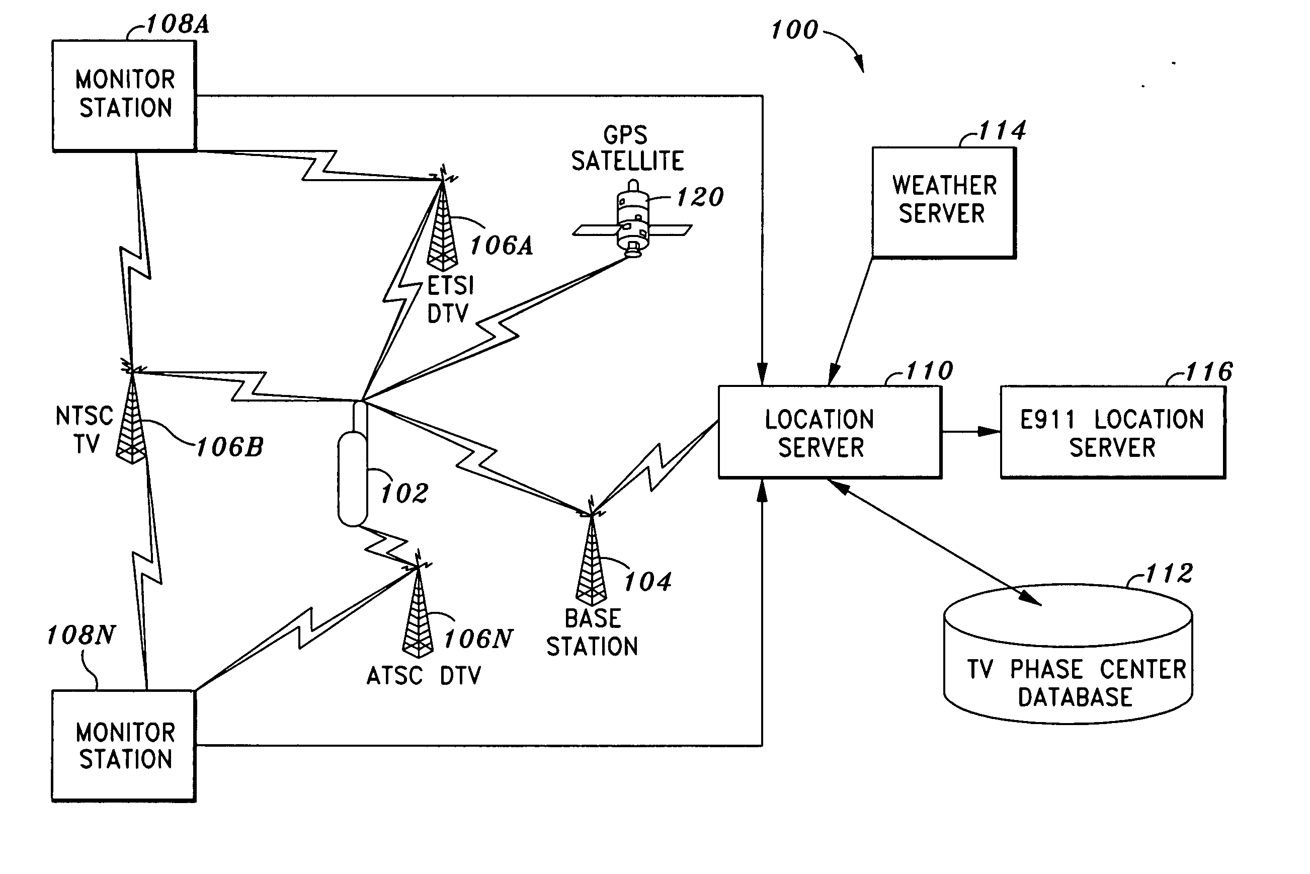
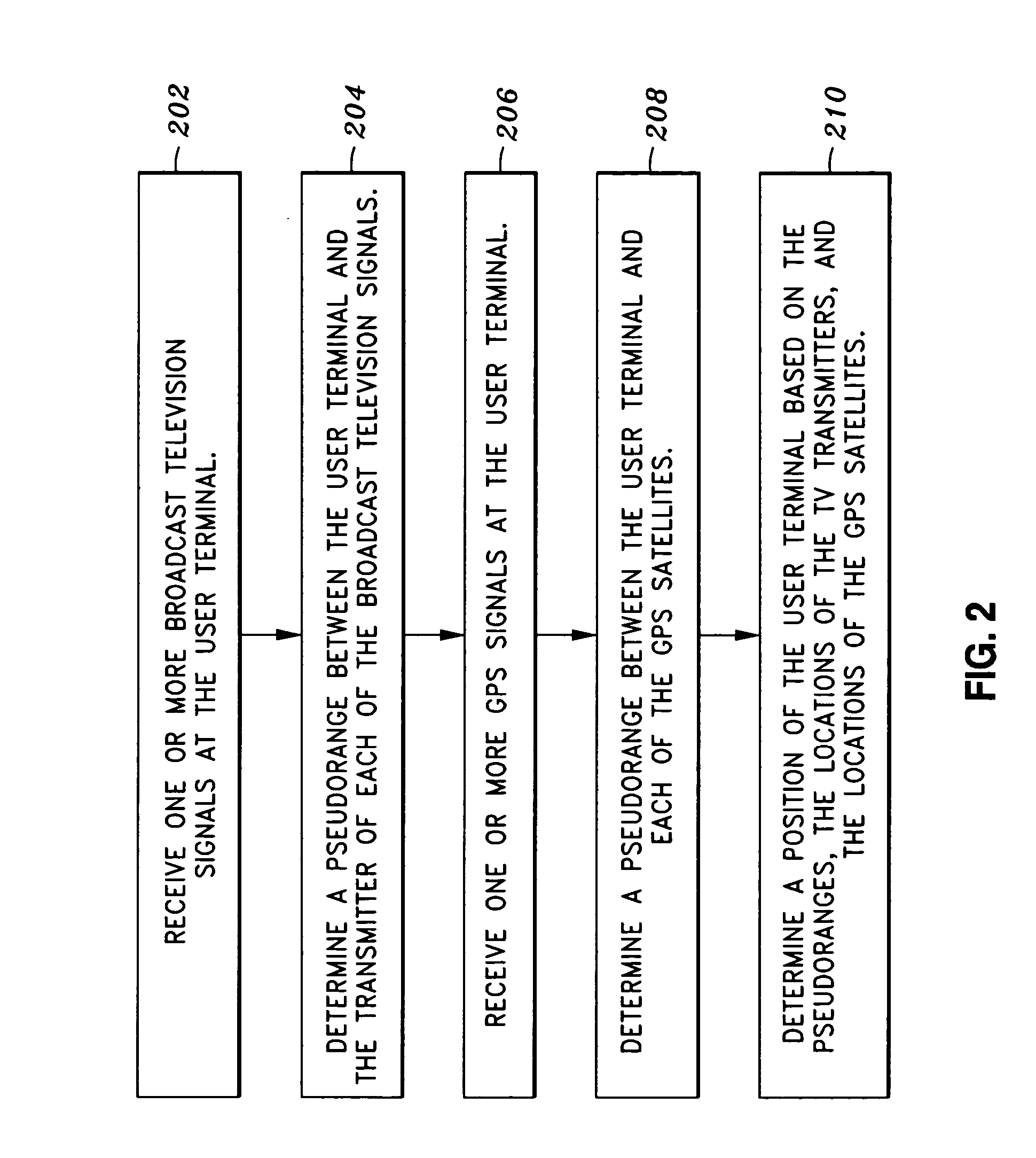
[0055] In general, in one aspect, the invention features a method and apparatus for receiving TV and GPS signals and determining position location in a manner that provides for rapid signal synchronization while minimizing receiver computational requirements. The invention also features a method and apparatus for coherent accumulation of intermediate frequency (IF) signals, which in turn permits real time or near real-time operation using a software implementation of the receiver. The invention further discloses a method for rapid open-loop acquisition of the pilot frequency of the received radio signal. The receiver described herein can be a receiver used either solely for receiving terrestrial or television broadcast signals, for receiving both television and GPS signals, or for receiving different types of television broadcast signals for position determination purposes. In certain embodiments, the receiver described herein is implemented in software on a microprocessor or genera...


PUM


Abstract

The present invention provides a method, system, and apparatus for estimating a pilot frequency of a television broadcast signal at a receiver. In one aspect, the receiver constitutes a mobile device that uses the estimated pilot frequency to facilitate the determination of position location of the mobile device. The receiver includes a processor which estimates the pilot frequency by computing a baseband version of the pilot signal relative to a reference frequency, defining time-shifted segments for the pilot signal and its baseband version, computing phase correction terms using the pilot signal and its baseband version, phase correcting each received signal segment, and estimating the pilot frequency. In another aspect of the invention, a phase-locked-loop is used to track the phase of the incoming pilot signal. The loop filter and / or the phase of the numerically controlled oscillator is scaled to account for the non-integer nature of samples within the received segments.

Description

CROSS-REFERENCES TO RELATED APPLICATIONS [0001] This application is related to U.S. Non-provisional patent application Ser. No. 10 / 003,128, “Robust Data Transmission Using Broadcast Digital Television Signals,” by Jimmy K. Omura, James J. Spilker, Jr. and Matthew Rabinowitz, filed Nov. 14, 2001; U.S. Non-provisional patent application Ser. No. 09 / 887,158, “Position Location using Broadcast Digital Television Signals,” by James J. Spilker and Matthew Rabinowitz, filed Jun. 21, 2001; U.S. Non-provisional patent application Ser. No. 09 / 932,010, “Position Location using Terrestrial Digital Video Broadcast Television Signals,” by James J. Spilker and Matthew Rabinowitz, filed Aug. 17, 2001; U.S. Non-provisional patent application Ser. No. 10 / 054,302, “Position Location using Broadcast Analog Television Signals,” by James J. Spilker and Matthew Rabinowitz, filed Jan. 22, 2002; U.S. Non-provisional Patent Applications Ser. No. ______ (TBS, Attorney Docket Number RSM008001), “Position Locat...

Claims


Application Information

Patent Timeline
Patent Type & Authority Applications(United States)
IPC IPC(8): H04N7/20
CPCG01S5/0036G01S19/46G01S19/25
Inventor RABINOWITZ, MATTHEWSABIN, MICHAEL J.OMURA, JIMMY K.
Owner ROSUM CORP
Learn More