Apparatus and methods for reducing stand-off effects of a downhole tool

a technology of stand-off effects and tools, applied in the field of tools for well logging, can solve the problems of difficult or impossible analysis of desired signals, difficult or impossible measurement, and the environment is extremely harsh, and achieve the effect of reducing the thickness of the mud layer

Inactive Publication Date: 2006-03-30
SCHLUMBERGER TECH CORP
View PDF32 Cites 31 Cited by
  • Summary
  • Abstract
  • Description
  • Claims
  • Application Information

AI Technical Summary

Benefits of technology

[0018] One aspect of the invention relates to downhole tools. A downhole tool in accordance with one embodiment of the invention includes an energy source and a receiver disposed on the downhole tool; at least one moveable section disposed between the energy source and the receiver; and an activation mechanism for reducing a thickness of a mud layer between the downhole tool and a wall of a borehole.

Problems solved by technology

Signal transmitted in the borehole may be generally referred to as “trapped signals,” which complicate the measurements and may render the analysis of the desired signals difficult or impossible.
An extremely harsh environment may be encountered by the antennas and electronics mounted in the pad and the cables connecting the pad to the drill collar.
Therefore, the mechanical abuse on an LWD pad in one LWD job is roughly three orders of magnitude greater than on a wireline pad in a wireline job.
Hence, abrasion of the antennas could be a significant problem leading to antenna failure and high maintenance and service costs.
Mechanical shock for components mounted in an articulated pad is another serious concern.
Furthermore, since the pad is small, lightweight, and articulated, the shock level will be considerably higher in the pad than in the drill collar.
Developing antennas and electronics to survive these shock levels is challenging.
Frictional contact between the pad and the formation may also result in the pad being subjected to much higher temperatures than the ambient downhole temperature.
While this approach overcomes some problems associated with rotating pads, it is sometimes desirable to have sensors rotate with the drill strings, for example to provide full-bore images.

Method used


Image

  • Apparatus and methods for reducing stand-off effects of a downhole tool
  • Apparatus and methods for reducing stand-off effects of a downhole tool
  • Apparatus and methods for reducing stand-off effects of a downhole tool

Examples


Embodiment Construction

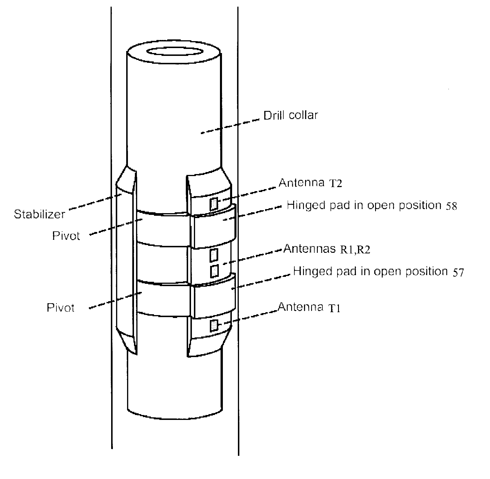
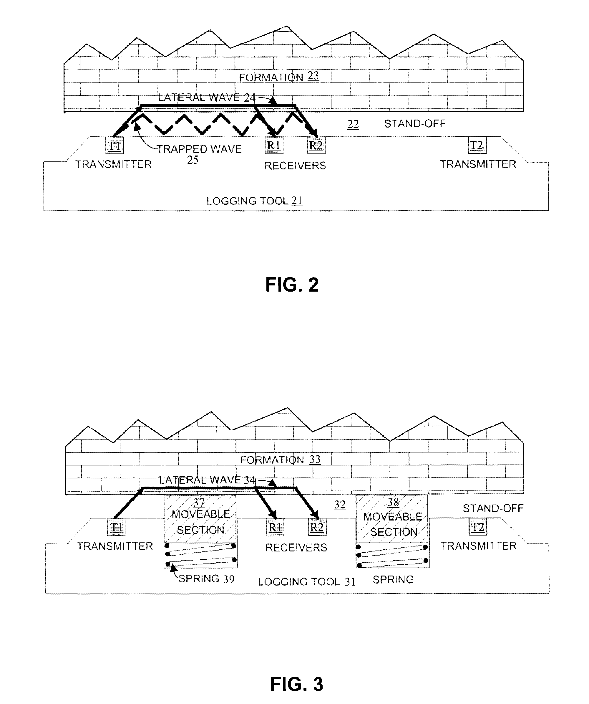
[0029] Embodiments of the invention relate to methods for reducing stand-off effects without mounting sensors (e.g., antennas) on articulated pads. In accordance with embodiments of the invention, the sensors or antennas (e.g., transmitters and receivers) may be mounted on the drill collars or stabilizers of a tool, and one or more articulating (deployable) pads are placed between the energy source (e.g., transmitters) and detectors (e.g., receivers). These pads may be articulated to eliminate or minimize the mud layer between the pads and the formation, and, therefore, to eliminate or minimize the transmission of the trapped signals. Embodiments of the invention is based on the concept of divorcing the sensors (e.g., antennas) from the articulated pad, while retaining the advantages of articulation.

[0030] Embodiments of the invention may be applied to any sensor or tool that is adversely impacted by trapped signals traveling in a mud layer between a source and a receiver. Such sen...


PUM


Abstract

A method for reducing stand-off effects of a downhole tool includes disposing the downhole tool in a borehole, wherein the downhole tool comprises at least one moveable section disposed between an energy source and a receiver on the downhole tool; and activating the at least one moveable section to reduce a thickness of at least one selected from a mud layer and a mudcake between the downhole tool and a wall of the borehole. A downhole tool includes an energy source and a receiver disposed on the downhole tool; at least one moveable section disposed between the energy source and the receiver; and an activation mechanism for reducing a thickness of at least one selected from a mud layer and a mudcake between the downhole tool and a wall of a borehole.

Description

CROSS-REFERENCE TO RELATED APPLICATIONS [0001] Not applicable. STATEMENT REGARDING FEDERALLY SPONSORED RESEARCH OR DEVELOPMENT [0002] Not applicable. BACKGROUND OF INVENTION [0003] 1. Field of the Invention [0004] The invention relates generally to tools for well logging. More particularly, the invention relates to devices and methods for reducing stand-off effects in downhole tools. [0005] 2. Background Art [0006] Oil and gas industry uses various tools to probe the formation to locate hydrocarbon reservoirs and to determine the types and quantities of hydrocarbons. A typical logging tool transmits energy (a signal) from a source (e.g., a transmitter of a propagation tool or a gamma-ray source of a density logging tool) into the borehole and the formation. The transmitted signal interacts with matters in the formation when it traverses the formation. As a result of these interactions, the properties of the transmitted signal is altered, and some of the altered signals may return to...

Claims


Application Information

Patent Timeline
Patent Type & Authority Applications(United States)
IPC IPC(8): E21B47/00G01V3/30
CPCG01V3/30E21B47/01E21B49/00
Inventor CLARK, BRIANSMITS, JAN W.
Owner SCHLUMBERGER TECH CORP
Why Eureka
Try Eureka