Flexible hydrogen delivery mechanism for storage and recovery of hydrogen

US20060065553A1Inactive Publication Date: 2006-03-30HERA USA

Image

  • Flexible hydrogen delivery mechanism for storage and recovery of hydrogen
  • Flexible hydrogen delivery mechanism for storage and recovery of hydrogen
  • Flexible hydrogen delivery mechanism for storage and recovery of hydrogen

Examples


Embodiment Construction

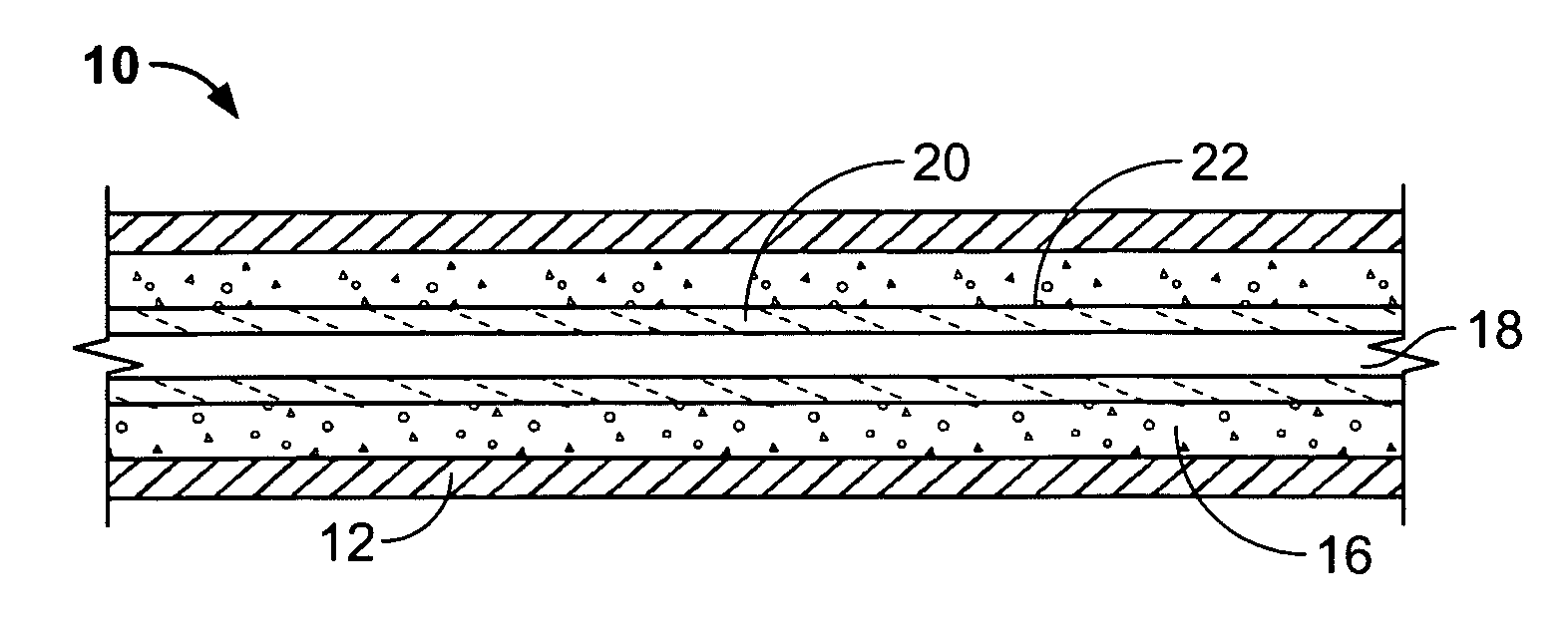
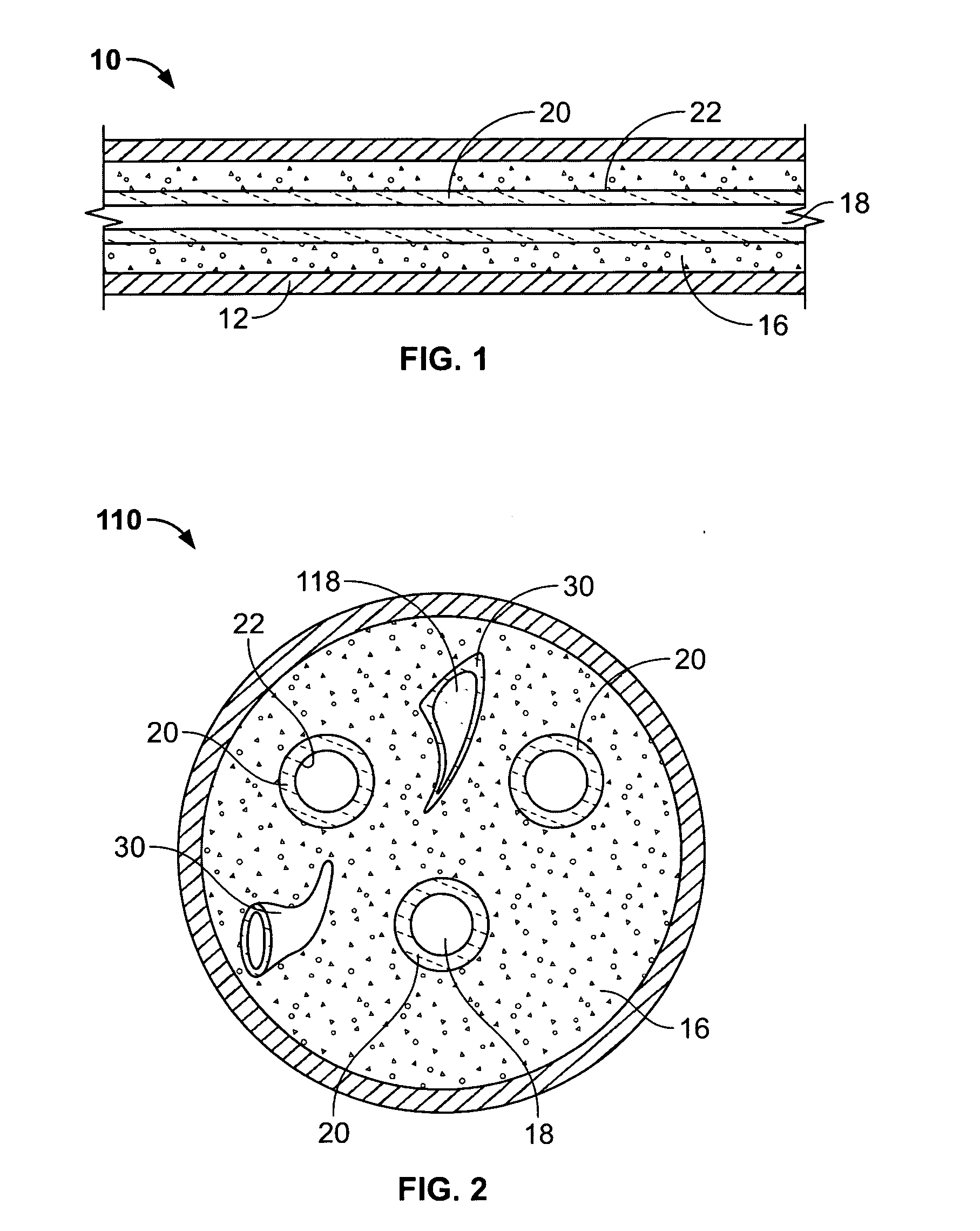
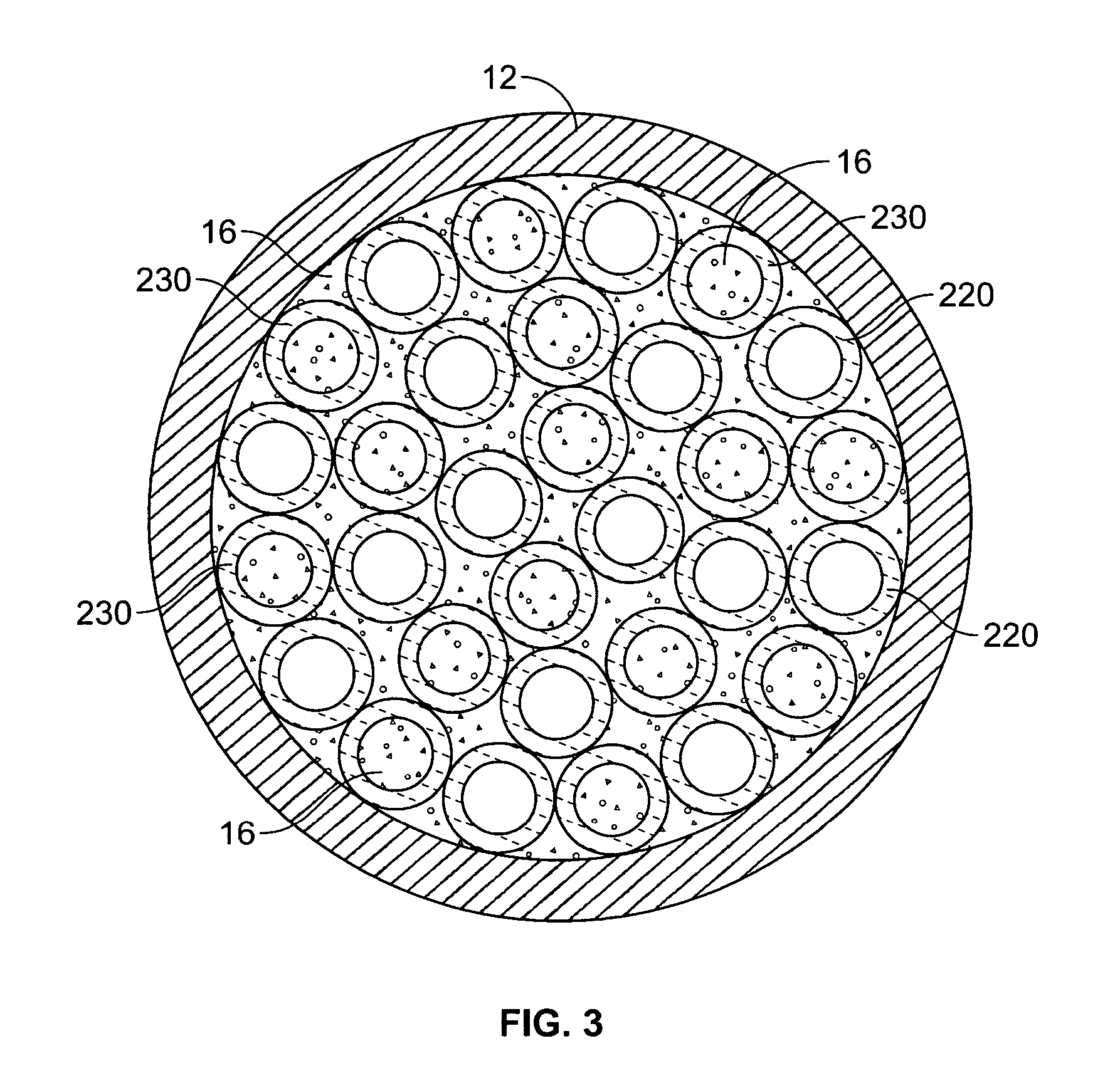
[0016] Referring now to FIG. 1, a generally tubular compartment unit 10 having a tubular wall 12 is shown in cross-section. For a more detailed description of the structure of the unit 10, including tubular walls 12, and the hydride material 16 contained by the wall 12, reference is made to the description found in commonly-owned U.S. Pat. No. 4,396,114, which description is incorporated herein by reference.

[0017] One significant difference from U.S. Pat. No. 4,396,114, providing a marked improvement and important feature of the present invention, is the ability to miniaturize the tubular unit 10, while simultaneously providing fluid communication within and through the tubular unit 10 so as to evenly distribute the hydrogen gas throughout the hydride material 16, along the entire length of the tubular unit. It has been suggested to use flexible helically wound springs, axially extending throughout the tubular unit 10. While the use of such closely wound springs to provide central ...


PUM

PropertyMeasurementUnit
Thicknessaaaaaaaaaa
Flexibilityaaaaaaaaaa
Compressive stressaaaaaaaaaa

Abstract

A conduit passage for use in transfer of hydrogen gas within a hydride system, including tubular members semi-permeable to hydrogen gas, permit hydrogen gas to pass through but not oxygen or other gases. The tubular members may comprise a flexible elastic polymeric material, such as polysulfone, polypropylene or polyethylene, including a central conduit passage, for providing hydrogen gas flow, the direction of the hydrogen flow depending on whether hydrogen is being absorbed or desorbed by the metal hydride. Simultaneously, the tube material, acting as a flexible spine, essentially fixes the hydride powder and prevents it from shifting about within the container, as well as being carried away in the hydrogen flow. Sections of the tubular member material may be interspersed throughout the hydride material to provide for peripheral hydrogen dispersion and to accommodate compressive stress forces that may develop as a result of the expansion of the hydride material during hydrogen absorption.

Description

BACKGROUND OF THE INVENTION [0001] 1. Field of the Invention [0002] This invention relates generally to an apparatus for transferring, storing and recovering hydrogen from a hydridable material and more particularly to such an apparatus used for transferring hydrogen under pressure while simultaneously removing any gaseous impurities from the hydrogen stream before the hydriding step. [0003] 2. Background Art [0004] Hydrogen in the combinant form of water has long been employed in many chemical processes. Recent advances have permitted use of elemental hydrogen in gaseous form in physical processes, such as in heat transfer and electrical energy storage. For example, the fuel cell industry, among others, is continually developing new applications for hydrogen, including fuel cells and heat transfer applications. As a result there is a growing need to store hydrogen safely and conveniently in such applications. [0005] Hydrogen has been stored conventionally as a gas in steel cylinder...

Claims


Application Information

Patent Timeline
30 Mar 2006
Publication
US20060065553A1
IPC
B65B3/00
CPC
F17C11/005; H01M8/04201; Y02E60/50; H01M8/065; Y02E60/321; H01M8/04208; Y02E60/32
Inventors
GOLBEN, P. MARK