Optical compensator element and liquid crystal display using the same

a liquid crystal display and compensator technology, applied in the field of optical compensator elements and liquid crystal displays using the same, can solve the problems of color tone or tone reversal, the inability to switch between a wide angle of visibility and a narrow angle of visibility, and the inability to carry out a simple operation. achieve the effect of simple operation

Inactive Publication Date: 2006-03-30
DAI NIPPON PRINTING CO LTD
View PDF3 Cites 81 Cited by
  • Summary
  • Abstract
  • Description
  • Claims
  • Application Information

AI Technical Summary

Benefits of technology

[0015] Unlike the conventional LCD in which, in use, an optical compensation film is applied to a display, according to the construction of the present invention, two transparent substrates are provided, an aligning layer, an electrode and the like are provided in each of the two transparent substrates so that one of the two transparent substrates on its side where the aligning layer, the electrode and the like have been provided faces the other transparent substrate on its side where the aligning layer, the electrode and the like have been provided, and a liquid crystal layer is held between the two transparent substrates, whereby the aligned state of th

Problems solved by technology

The reason for this is that increasing the angle of visibility causes leakage of light from pixels which should display black, resulting in a change in color tone or tone reversal or the like.
In a construction in which an optical compensation film (a phase difference film) for realizing a wide angle of visibili

Method used


Image

  • Optical compensator element and liquid crystal display using the same
  • Optical compensator element and liquid crystal display using the same
  • Optical compensator element and liquid crystal display using the same

Examples


example 1

(1) Preparation of Optical Compensator Element

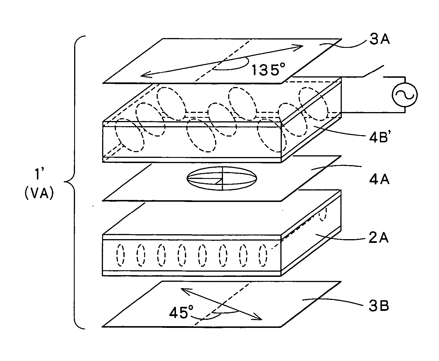
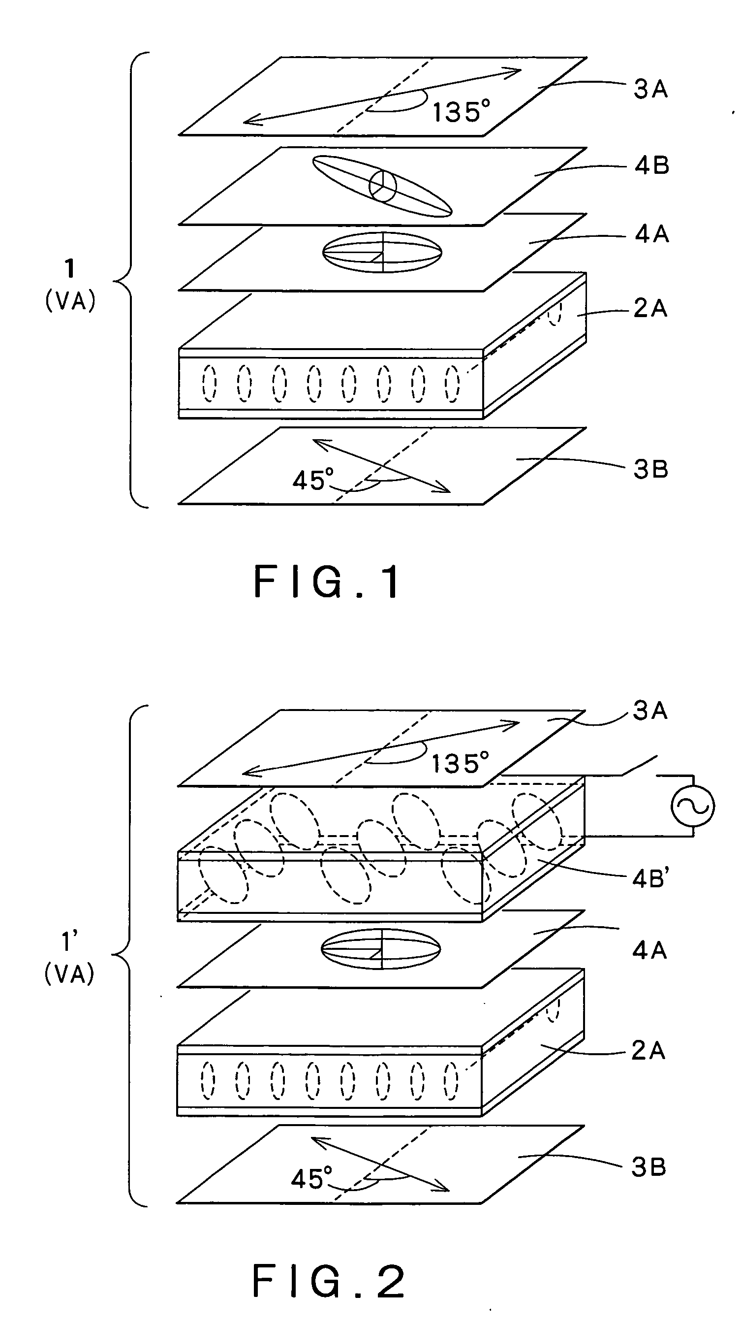
[0045] An ITO thin film was formed as a transparent electrode on a glass substrate subjected to cleaning (part number: 1737, manufactured by Corning Incorporated). Next, a polyimide resin aligning agent (tradename “OPTMER AL1254”, manufactured by JSR Corporation) was applied by flexographic printing on the ITO thin film, and the print was heat dried, followed by rubbing treatment to form an aligning film. The two glass substrates on which the transparent electrode and the aligning film had been formed thus obtained were provided and were disposed so that the aligning film sides face each other. A spacer (spherical particles with a diameter of 2 μm; tradename “Micropearl”, manufactured by SEKISUI CHEMICAL CO.,LTD.) was provided between the two substrates, and the peripheries of the two substrates were bonded to each other through the spacer. The space within the laminated glass substrates was filled with a liquid crystal material having...

example 2

(1) Preparation of IPS-Mode LCD

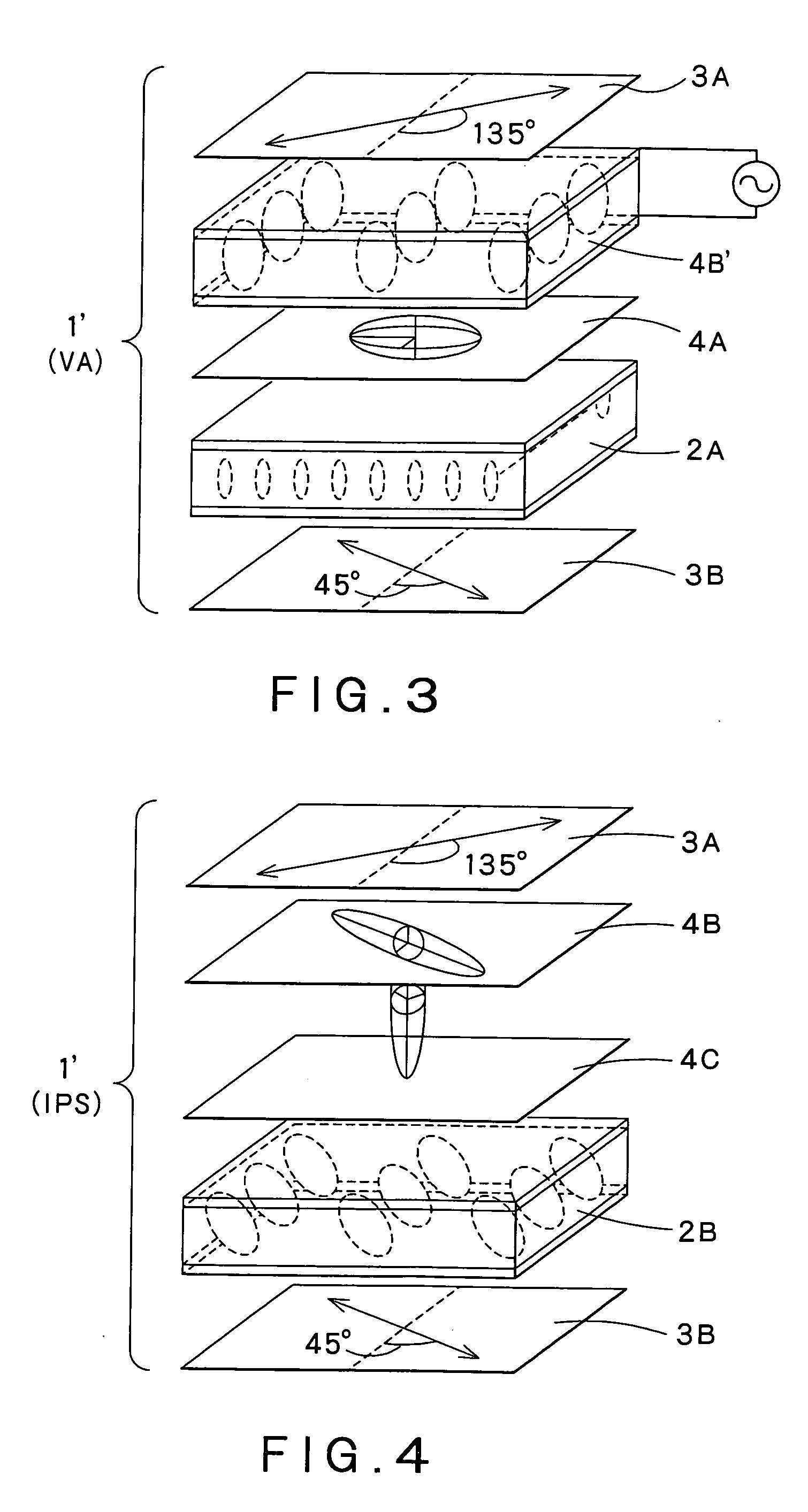
[0048] An IPS-mode LCD was prepared in the same manner as in the optical compensator element of Example 1, except that beads with a diameter of 3.5 μm were used as the spacer, a horizontally aligning film subjected to rubbing treatment was formed as an aligning film on the substrate, and a liquid crystal material having positive dielectric anisotropy was used as the liquid crystal material.

(2) Preparation of IPS-Mode LCD Which Can Realize Switching Between Wide Angle of Visibility and Narrow Angle of Visibility

[0049] A positive C plate and the optical compensator element as prepared in Example 1 were stacked in that order on the IPS-mode LCD prepared above. One polarizing plate was stacked under the IPS-mode LCD, and another polarizing plate was stacked on the optical compensator element so that the polarization direction of one polarizing plate was orthogonal to the polarization direction of the other polarizing plate.

[0050] Black display was pr...


PUM


Abstract

Disclosed are an optical compensator element, which can realize switching between a wide angle of visibility and a narrow angle of visibility through a simple operation, and a liquid crystal display using the same. An optical compensation layer 4B′ comprising, for example, a liquid crystal material having positive dielectric anisotropy sealed between two substrates comprising a transparent electrode and an aligning film stacked on top of each other is provided. An optical compensation layer 4A as a negative C plate and the optical compensation layer 4B′ are stacked in that order on a homeotropically aligned liquid crystal cell 2A to constitute a liquid crystal display 1. Upon the application of voltage to the optical compensation layer 4B′, a narrow angle of visibility is provided, while, when no voltage is applied, a wide angle of visibility is provided.

Description

BACKGROUND OF THE INVENTION [0001] 1. Field of the Invention [0002] The present invention relates to an optical compensator element, in which the level of phase difference is variable by the application of voltage, and a liquid crystal display using the same. [0003] 2. Background Art [0004] Liquid crystal displays (hereinafter referred to as “LCDs”) have features of thin, lightweight, low power consumption, and freedom from flicker. For this reason, LCDs are extensively used in various displays, that is, large stationary displays, as well as displays of portable terminal equipment and the like. [0005] In the case of portable terminal equipment, what is sometimes required of displays is that display can be seen only by the user while the display cannot be seen by a person(s) around the user. On the other hand, in some cases, display should be positively seen by a person(s) around the display. These are true of large and stationary displays. [0006] In recent years, spread of digital s...

Claims


Application Information

Patent Timeline
IPC IPC(8): G02F1/1335G02B5/30G02F1/133G02F1/13363G02F1/1347
CPCG02F1/1323G02F1/13471G02F1/133634
Inventor MORIYA, NORIHISA
Owner DAI NIPPON PRINTING CO LTD
Why Eureka
Try Eureka