System and method for placement of RDMA payload into application memory of a processor system

a processor system and payload technology, applied in the field of network interfaces, can solve the problems of increasing the workload of enterprise data centers, and putting considerable pressure on enterprise data centers

Inactive Publication Date: 2006-03-30
AMMASSO
View PDF32 Cites 85 Cited by
  • Summary
  • Abstract
  • Description
  • Claims
  • Application Information

AI Technical Summary

Problems solved by technology

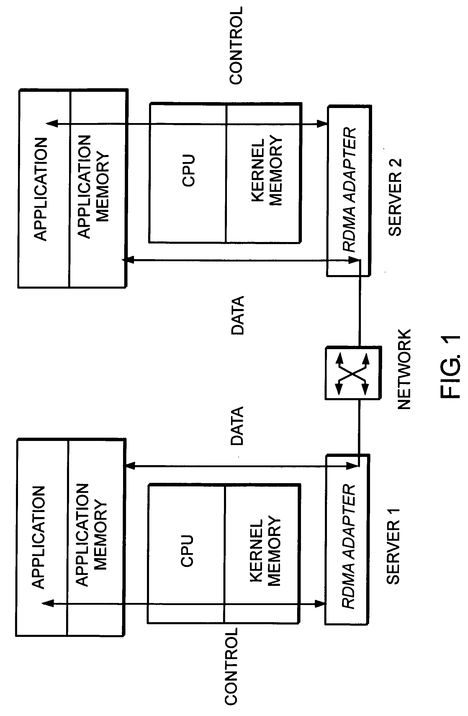
Implementation of multi-tiered architectures, distributed Internet-based applications, and the growing use of clustering and grid computing is driving an explosive demand for more network and system performance, putting considerable pressure on enterprise data centers.
Combined with the added problem of ever-increasing amounts of data that need to be transmitted, data centers are now facing an “I/O bottleneck”.
This bottleneck has resulted in reduced scalability of applications and systems, as well as, lower overall systems performance.
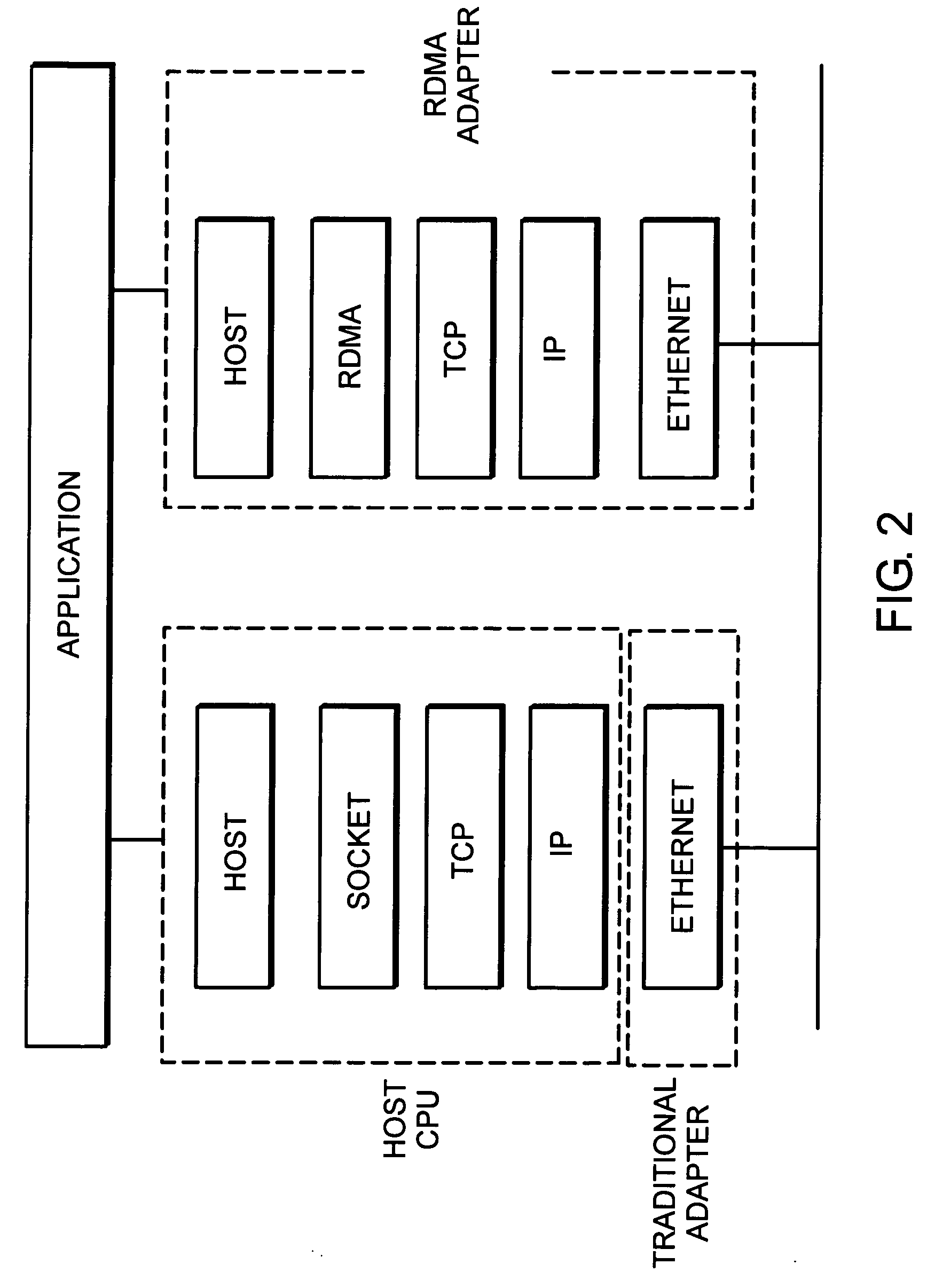
However, a TOE does not completely reduce data copying, nor does it reduce user-kernel context switching—it m

Method used


Image

  • System and method for placement of RDMA payload into application memory of a processor system
  • System and method for placement of RDMA payload into application memory of a processor system
  • System and method for placement of RDMA payload into application memory of a processor system

Examples


Embodiment Construction

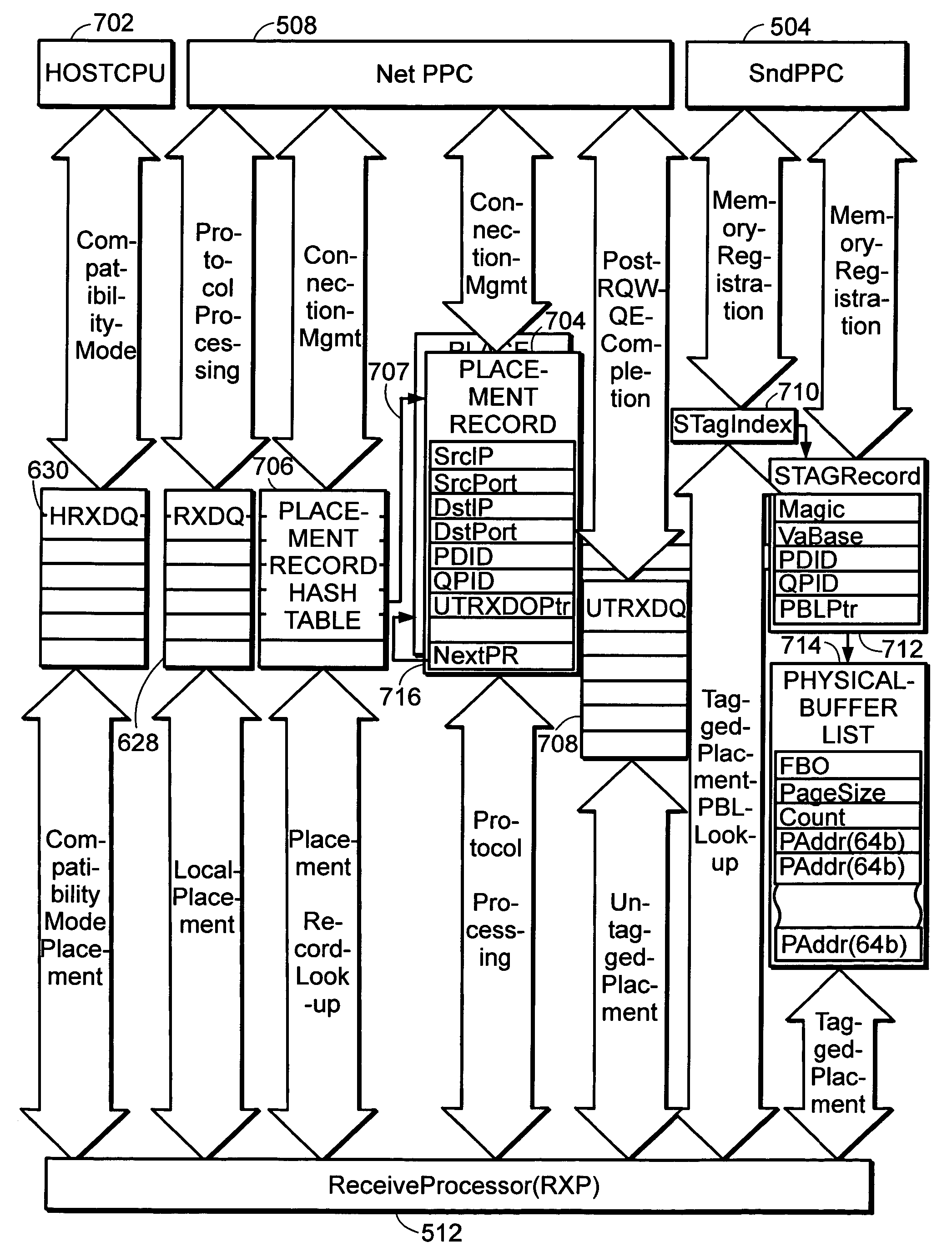
[0051] Preferred embodiments of the invention provide a method and system that efficiently places the payload of RDMA communications into an application buffer. The application buffer is contiguous in the application's virtual address space, but is not necessarily contiguous in the processor's physical address space. The placement of such data is direct and avoids the need for intervening bufferings. The approach minimizes overall system buffering requirements and reduces latency for the data reception.

[0052]FIG. 4 is a high-level depiction of an RNIC according to a preferred embodiment of the invention. A host computer 400 communicates with the RNIC 402 via a predefined interface 404 (e.g., PCI bus interface). The RNIC 402 includes an message queue subsystem 406 and a RDMA engine 408. The message queue subsystem 406 is primarily responsible for providing the specified work queues and communicating via the specified host interface 404. The RDMA engine interacts with the message que...


PUM


Abstract

A system and method for placement of RDMA payload into application memory of a processor system. Under one embodiment, a network adapter system is capable of use in network communication in accordance with a direct data placement (DDP) protocol, e.g., RDMA. The network adapter system includes adapter memory and a plurality of placement records in the adapter memory. Each placement record specifies per-connection placement data including at least network address information and port identifications of source and destination network entities for a corresponding DDP protocol connection. Placement record identification logic uniquely identifies a placement record from network address information and port identification information contained in a DDP message received by the network adapter system. Untagged message payload placement logic directly places the payload of the received untagged DDP message into physical address locations of host memory corresponding to one of said connection-specific application buffers. Tagged message payload placement logic directly places the payload of the tagged DDP message into physical address locations of host memory corresponding to the identifier in the received DDP message. According to one embodiment, the placement records are organized as an array of hash buckets with each element of the array containing a placement record and each placement record containing a specification of a next placement record in the same bucket. The placement record identification logic includes hashing logic to create a hash index pointing to a bucket in the array by hashing a 4-tuple consisting of a source address, a destination address, a source port, and a destination port contained in the received DDP message.

Description

CROSS-REFERENCE TO RELATED APPLICATIONS [0001] This application claims priority under 35 U.S.C. §119(e) to U.S. Provisional Patent Application No. 60 / 559,557, filed on Apr. 5, 2004, entitled SYSTEM AND METHOD FOR REMOTE DIRECT MEMORY ACCESS, which is expressly incorporated herein by reference in its entirety. [0002] This application is related to U.S. patent application Nos. <to be determined>, filed on even date herewith, entitled SYSTEM AND METHOD FOR WORK REQUEST QUEUING FOR INTELLIGENT ADAPTER and SYSTEM AND METHOD FOR PLACEMENT OF SHARING PHYSICAL BUFFER LISTS IN RDMA COMMUNICATION, which are incorporated herein by reference in their entirety.BACKGROUND [0003] 1. Field of the Invention [0004] This invention relates to network interfaces and more particularly to the direct placement of RDMA payload into processor memory. [0005] 2. Discussion of Related Art [0006] Implementation of multi-tiered architectures, distributed Internet-based applications, and the growing use of c...

Claims


Application Information

Patent Timeline
IPC IPC(8): H04L12/56G06F12/10
CPCG06F12/1081
Inventor TUCKER, TOMJIA, YANTAO
Owner AMMASSO
Why Eureka
Try Eureka