Control of delay line interferometer

Active Publication Date: 2006-03-30
RPX CORP +1
View PDF3 Cites 30 Cited by
  • Summary
  • Abstract
  • Description
  • Claims
  • Application Information

AI Technical Summary

Benefits of technology

[0012] An embodiment of the present invention is a technique that makes use of FEC decoders, thereby reducing cost by reusing apparatus, and, at the same

Problems solved by technology

As the implementation of such a device in the electrical domain gives rise to difficulties, it has been proposed to implement such a function in the optical domain using an optical delay line interferometer (DLI).
Since interferometers rely for their operation on the constructive/destructive interference between two optical fields, a DLI is particularly sensitive to the setting of the delay.
The normal methods of providing automatic control in receiver equipment do not readily transfer to the control of the delay in a DLI, or else they involve substantial extra expense.
This requires a degree of deliberate misalignment of the phase modulation, in that instead of the ph

Method used


Image

  • Control of delay line interferometer
  • Control of delay line interferometer
  • Control of delay line interferometer

Examples


Example

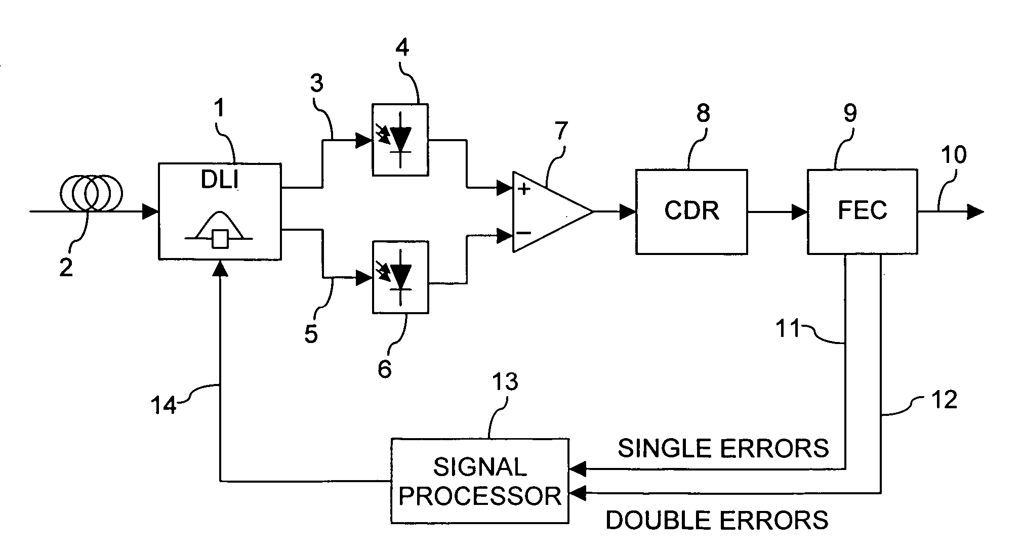
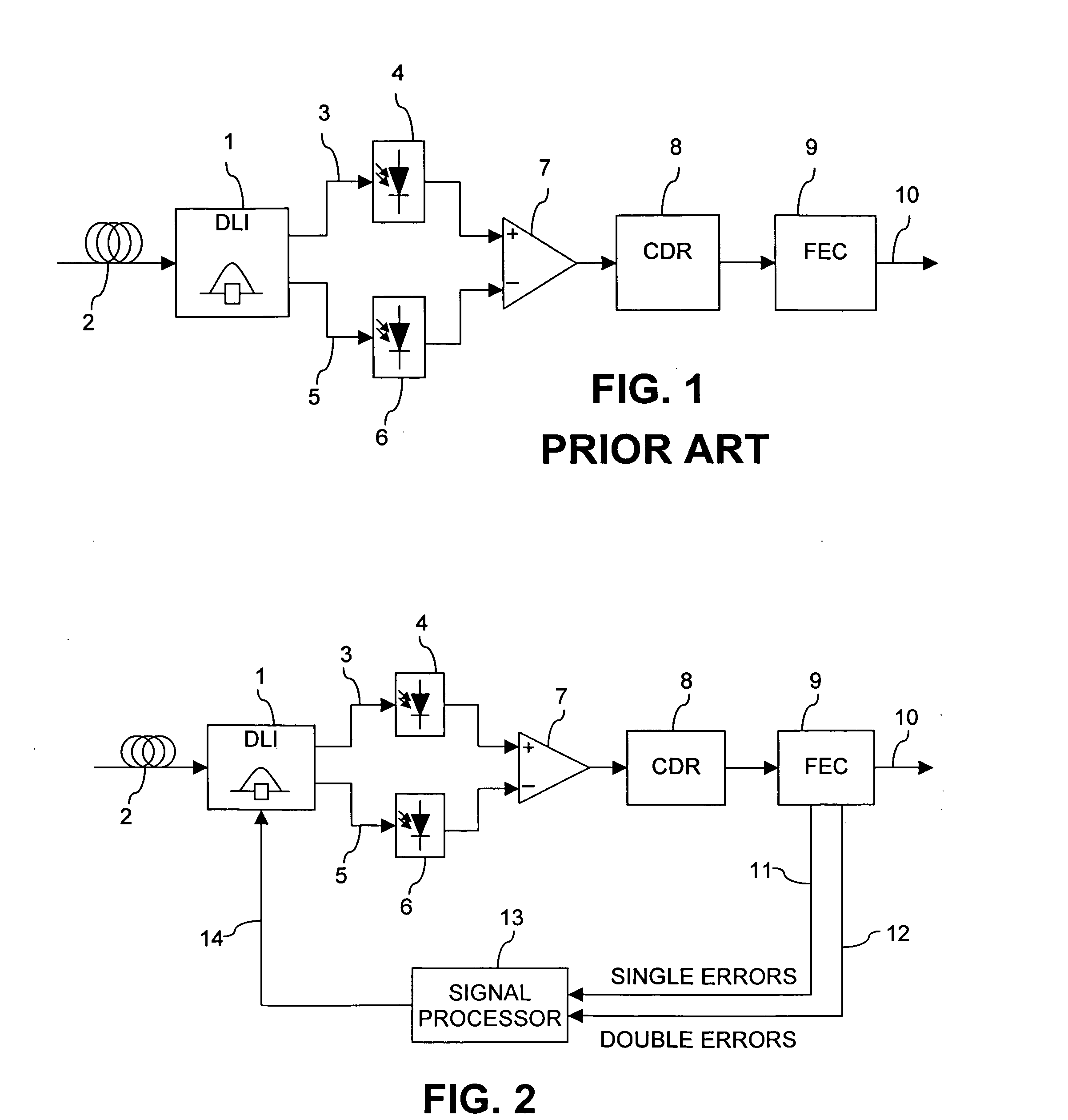
[0019]FIG. 1 shows the general layout of a receiver for optical DPSK signals. A delay-line interferometer (DLI) 1 is connected to receive optical DPSK signals from an optical fiber link 2. The DLI is constructed on the principles of a Mach-Zehnder interferometer, with one arm incorporating a delay of one bit length of the DPSK signal relative to the other arm.

[0020] The DLI has a sum output 3 which provides a signal which is the sum of the optical signal in one bit period with the optical signal in the next bit period, and is therefore of high intensity when there is no phase difference between the optical signals in the two bit periods, and of approximately zero intensity when there is a phase difference of π radians between the two signals. The signal from the sum output 3 is applied to a first photo-detector 4 which detects the signal. The DLI also has a difference output 5 which provides a signal which is the difference between the optical signal in one bit period and the optic...


PUM


Abstract

The delay setting of an optical delay line interferometer (DLI) used to decode differentially encoded phase shift keyed signals (DPSK or DQPSK) is controlled using a control signal representative of the ratio Perr2/Perr1 of the rate of occurrence of double errors and the rate of occurrence of errors. The ratio Perr2/Perr1, as the delay setting of the DLI is varied, exhibits a characteristic W-shaped structure consisting of a local maximum at the optimum value and two minima adjacent to the maximum, one on each side of it. This structure is present over a wide range of signal to noise ratio and residual dispersion.

Description

TECHNICAL FIELD [0001] This invention relates to data transmission via optical signals, and especially to a method and device for automatic control of a delay line interferometer. BACKGROUND OF THE INVENTION [0002] The need for bandwidth and reach in optical transmission has given rise to a need to use more advanced modulation formats. While, at the present, amplitude modulation is still the predominant format, advanced modulation formats often make use of phase modulation. Among the advanced modulation formats that are likely to be implemented first, owing to their simplicity, are optical duobinary (ODB), differential phase shift keying (DPSK), and differential quadrature phase shift keying (DQPSK). [0003] For some modulation formats (such as ODB, DPSK and DQPSK), a logical exclusive-OR (or modulo 2 addition) is necessary in the modulator or demodulator. As the implementation of such a device in the electrical domain gives rise to difficulties, it has been proposed to implement suc...

Claims


Application Information

Patent Timeline
IPC IPC(8): H04B10/00
CPCG02B6/389H04L27/18H04B10/66G02B6/3894
Inventor HAUNSTEIN, HERBERTSCHLENK, RALPH
Owner RPX CORP
Why Eureka
Try Eureka