[0015] The present invention in its several disclosed embodiments alleviates the drawbacks described above with respect to methods and systems for raising, leveling, supporting and repairing existing damaged foundations and incorporates several additional beneficial features. The present invention described herein is an apparatus and method for raising, leveling, and supporting an uneven structural foundation by placing piers at necessary points directly beneath the foundation and driven to a depth which allows the structure's foundation to be raised with a jack. The piers are constructed preferably from piling segments which are driven into the ground, connected with
adhesive, and anchored at a depth which offers a reactive force suitable to support the slab beam above. Each
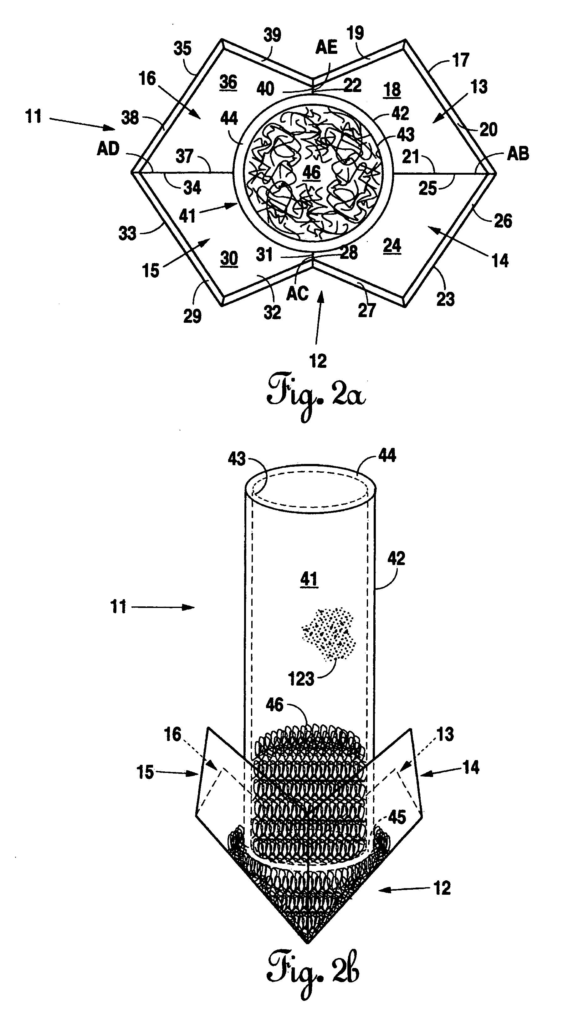
pier is pointed at its bottom end and deepest point in order to facilitate
insertion and prevent upheaval. A crown is attached to the piers which offers a platform to place a jack and raise the slab to a stable supportive position and provide for easy access to the slab beam for later readjustment. In a preferred embodiment, multiple piers may be utilized to achieve a level foundation. An
advantage of the present invention is the piers are positioned beneath the structure's foundation thereby eliminating the need for a complex anchoring
system which only tangentially addresses the inherent problem in the design. Second, the piers are made of inexpensive but strong hollow steel pipes which provide for lower driving force, strength, durability, and time advantages over
cement piers. The present invention also introduces a pointed
starter segment which further lowers the driving force and installation time by acting as a pierce when inserted into the earth to move obstacles which may dent the
pier structure. After installation, the pointed started segment acts as an anchor preventing upheaval due to soil expansion, a problem encountered by all pier systems.
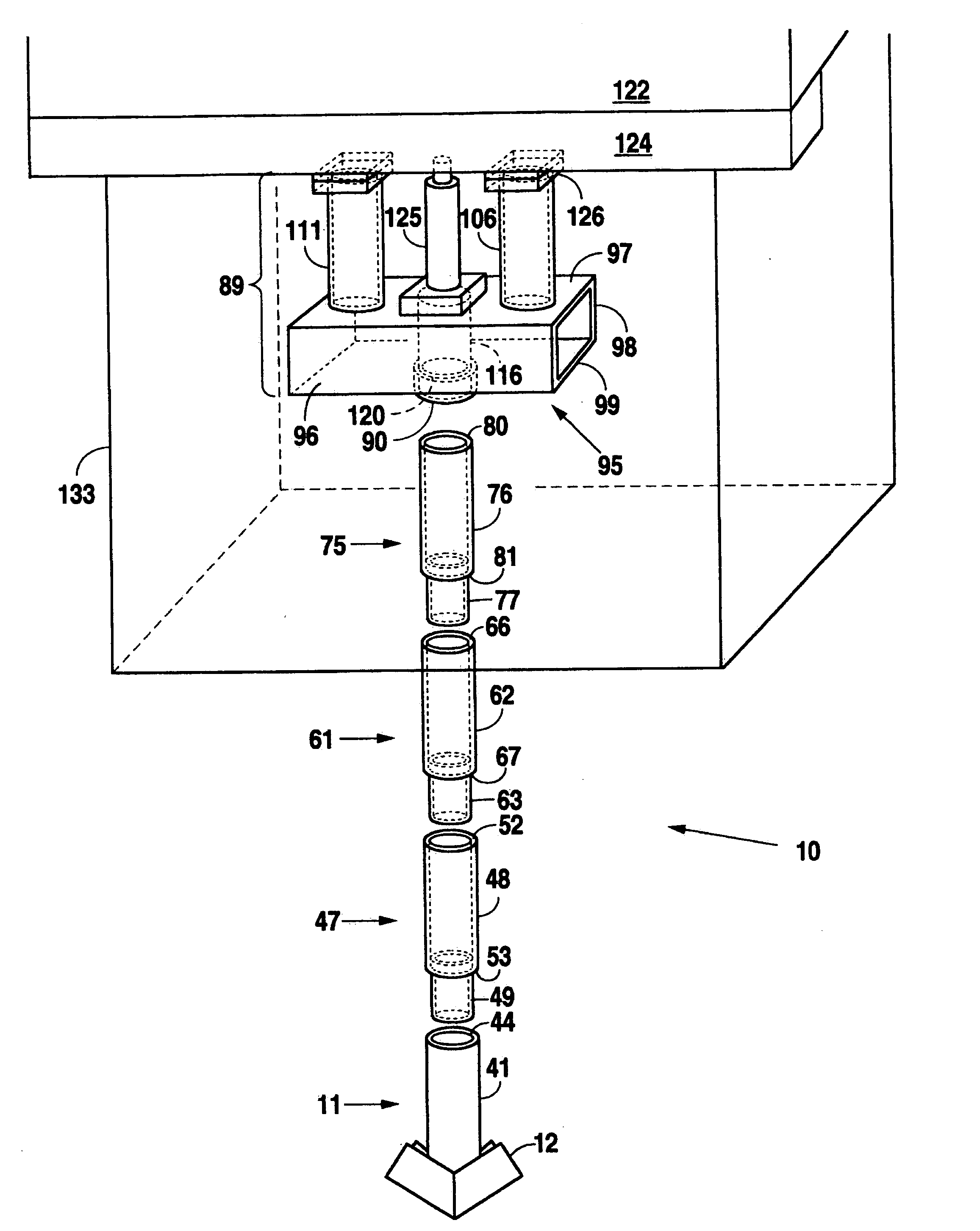
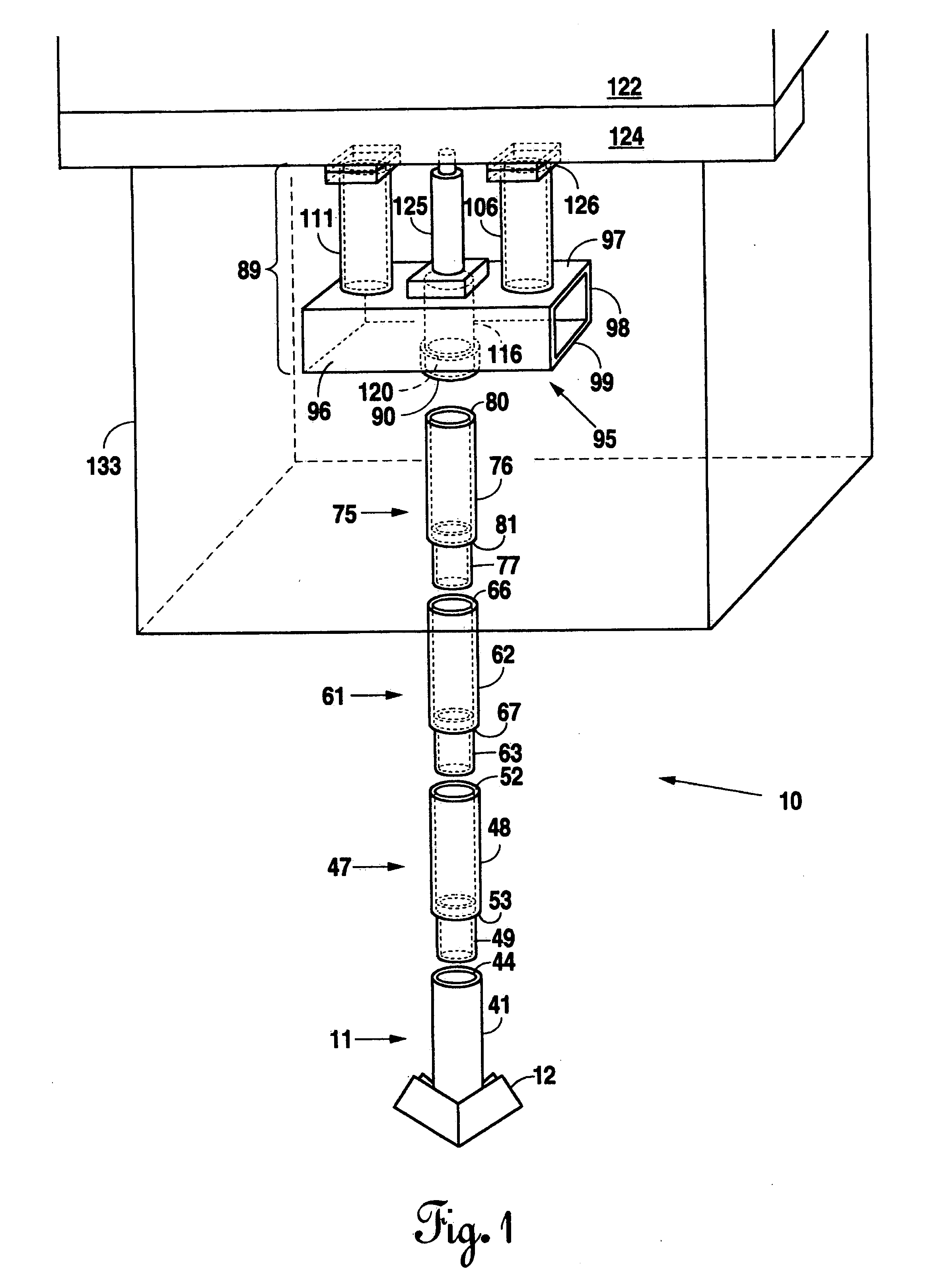
[0016] Initially, holes are dug in the earth directly beneath the foundation where leveling is sought. A piling
starter segment is driven vertically into the ground beneath the slab beam using a driver such as a
hydraulic ram. Additional piling segments are attached to the
starter segment to form a pier and are driven deeper into the earth until the reactive force (pressure) reaches an adequate level to support the foundation. The pier is capped with the crown which comprises of a collar, a horizontal base member, a base member support inset and two vertical support members. A jack is positioned on the crown which acts as both a platform for the jack and a support structure on which the slab beam may rest. The jack is then used to lift the slab and shims are placed atop the support members of the crown until they contact the underside of the slab beam. Finally, the jack is removed and the hole is then covered.
[0017] An additional
advantage of the present invention is the piers are coated to prevent
corrosion. Specifically, the pilings are sealed together not only to increase the overall stability of the structure by resisting bending, but also to seal joints from
moisture, another common problem of hollow piers. The starter segment is also internally sealed providing additional strength to the segment and preventing
weakness from
corrosion from moisture and the like.
[0018] The present invention also includes a
pile cap or “crown” designed to increase stability. The crown increases the contact surface area between the pier and the slab beam by utilizing two support members upon which shims are placed. These support members are placed such that access to the beam is as easy on its first use as on any subsequent re-leveling procedures that may be required. Also, later adjustment is similarly easy because anyone with a jack may access the pier and readjust the level of the slab even if that person has no expertise on the installation method or the apparatus. Overall, this invention maintains the advantages of being placed beneath the foundation over being inserted in an adjacent manner, of using steel piers over
cement piers, of using and adjustable pier over a non-adjustable one, but in the aggregate offers a
system that decreases installation time, increases stability, decreases
corrosion, and offers easy access for readjustment.
[0019] Interior slab beams may also be supported and leveled without having to
drill interior access holes in the concrete slab to access the beams interior to the periphery of the slab. To reach interior slab beams a hole or tunnel can be dug from the outside edge to the point under the foundation where the pier is to be placed and then follow the method of this invention to level the foundation. Because the piers are small and easy to
handle they can be easily positioned at the beams interior to the periphery of the slab through the tunnel under the slab.
[0020] Further advantages of this invention when compared to prior art is its more stable and stronger design, its quick installation, its durability and resistance to corrosion, its adjustability after installation, and its ease of use and access to those not familiar with the invention. Older methods and apparatuses either relied on an adjacent driving
system which invoked stability problems or on
cement pilings which invoked problems such the necessity of higher driving force, the susceptibility to corrosion, and prolonged installation time. This invention offers the
advantage of direct, stable, and durable support to re-level a displaced foundation which can later be easily readjusted.

