

Turbocharger with titanium component
a technology of titanium components and turbochargers, which is applied in the direction of blade accessories, waterborne vessels, machines/engines, etc., can solve the problems of affecting the performance of the turbine, and affecting the efficiency of the turbin
- Summary
- Abstract
- Description
- Claims
- Application Information
AI Technical Summary
Problems solved by technology
Method used
Image

Examples
Embodiment Construction
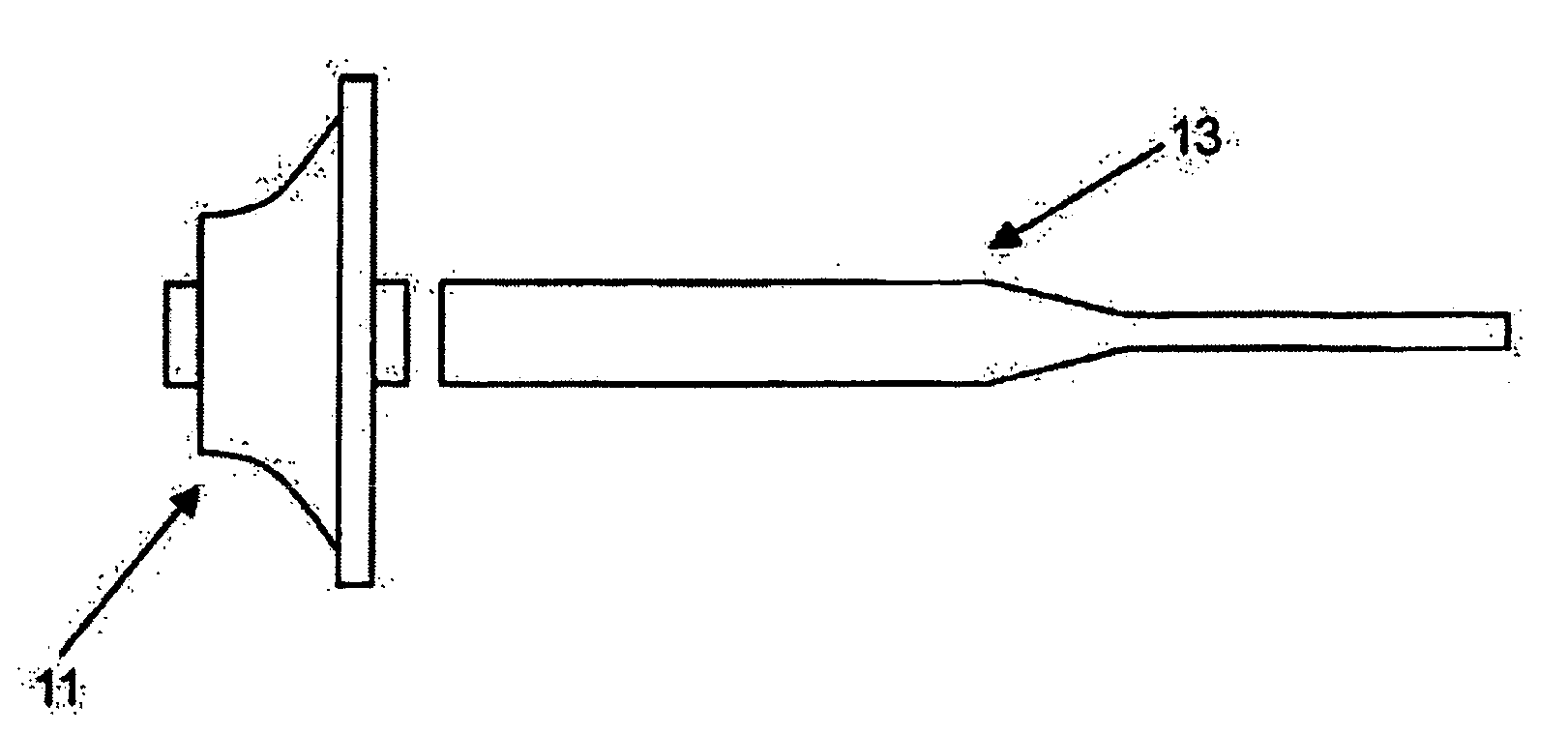
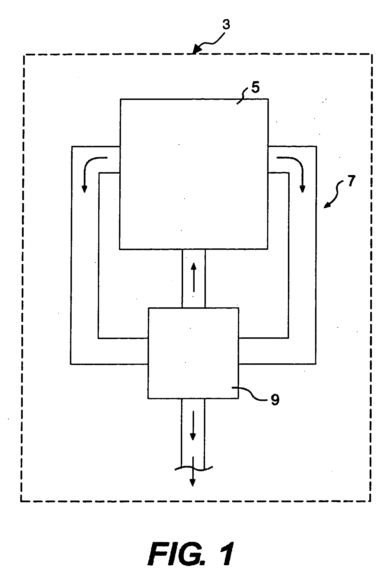
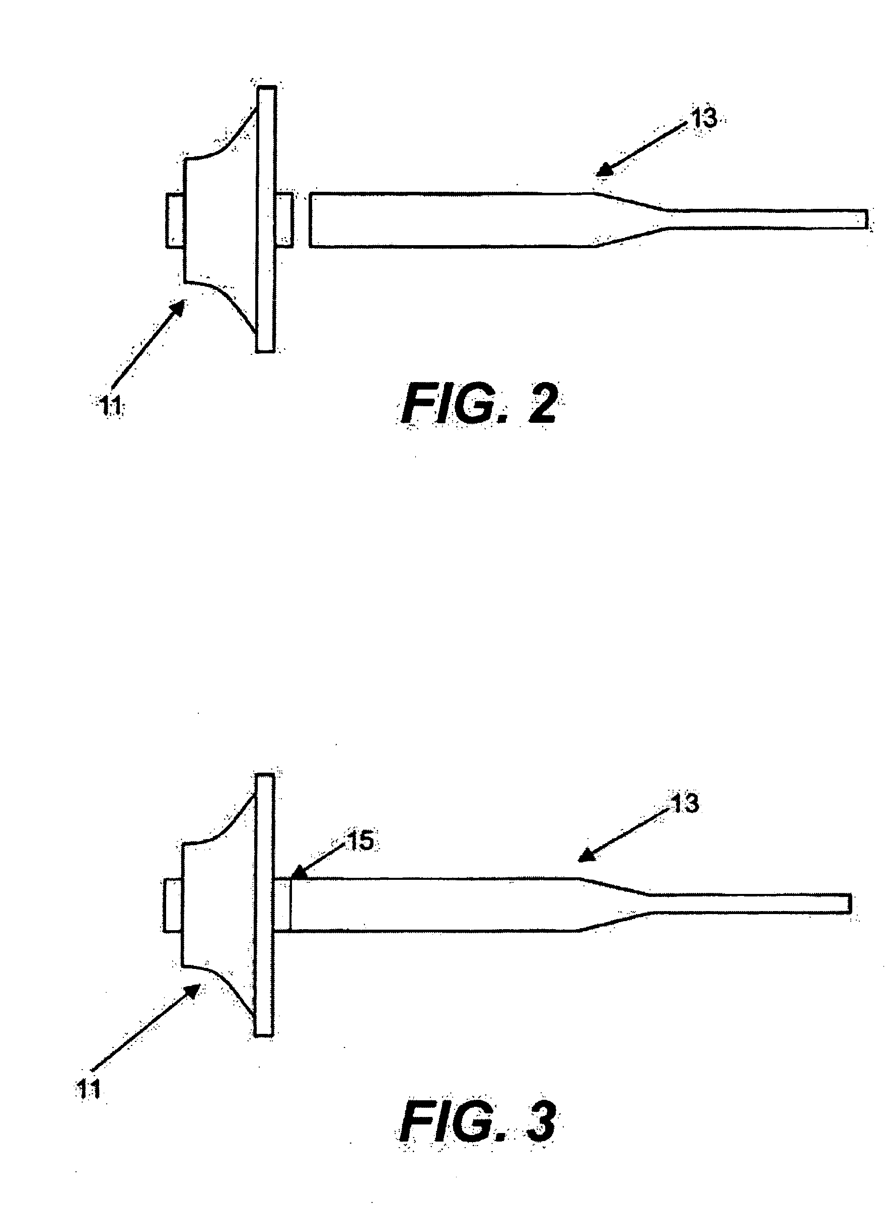
[0015]FIG. 1 provides a block diagram of a work machine 3 of the present disclosure including a power source 5, an exhaust system 7, and a turbocharger 9. Turbocharger 9 includes a turbine 11, a shaft 13, and a single joint 15, as shown in FIGS. 2-3. The turbocharger 9 may increase the power output of power source 5.
[0016] In one embodiment, turbocharger turbine 111 may include titanium-aluminide, and turbocharger shaft 13 may include titanium. Turbocharger turbine 11 and turbocharger shaft 13 may be operably connected at single joint 15, as shown in FIG. 3. Joint 15 may be made in a variety of ways. For example, gas tungsten-arc welding, gas metal-arc welding, resistance welding, laser welding, plasma arc welding, electron-beam welding, friction welding, brazing, soldering, or any other joining method may be used to form joint 15. In one embodiment, joint 15 may include a friction weld joint, an electron-beam weld joint, or a laser weld joint.
[0017] Turbine 11 and shaft 13 may be...
PUM
| Property | Measurement | Unit |
|---|---|---|
| Stiffness | aaaaa | aaaaa |
Abstract
Description
Claims
Application Information