Golf ball

a golf ball and ball technology, applied in the field of golf balls, can solve the problems of not reducing aerodynamic resistance so effectively, and achieve the effect of improving aerodynamic performance and long flying distan

Inactive Publication Date: 2006-03-30
BRIDGESTONE SPORTS
View PDF3 Cites 20 Cited by
  • Summary
  • Abstract
  • Description
  • Claims
  • Application Information

AI Technical Summary

Benefits of technology

[0008] The present invention was completed in view of the foregoing. It is an object of the present invention to provide a golf ball which has improved aerodynamic performance due to dimples and achieves a long flying distance.
[0009] After their extensive researches to achieve the above-mentioned object, the present inventors found that a golf ball having a number of dimples separated by edges on its surface exhibits improved aerodynamic performance due to dimples if the edges are formed from two or more edge elements joined together such that all or part of the joined parts as viewed from above are smoothly curved. The present invention is based on this finding.
[0010] In general, the flight performance of a golf ball is affected by the total area of dimples that accounts for in the surface area of the golf ball. The greater the total area of dimples, the better the aerodynamic performance. The present invention is characterized in that the shape of the flat part or land is optimized so as to maximize the total area of the dimples. The golf ball designed in this manner has much better aerodynamic performance than conventional ones. An increase in the total area of dimples on the ball surface means a decrease in the area of flat parts. The present inventors found that the shape of flat parts separating dimples from each other greatly affects the flying distance of the golf ball. The present invention provides the golf ball defined in the following.

Problems solved by technology

Therefore, they do not reduce aerodynamic resistance so effectively.

Method used


Image

  • Golf ball
  • Golf ball
  • Golf ball

Examples


examples

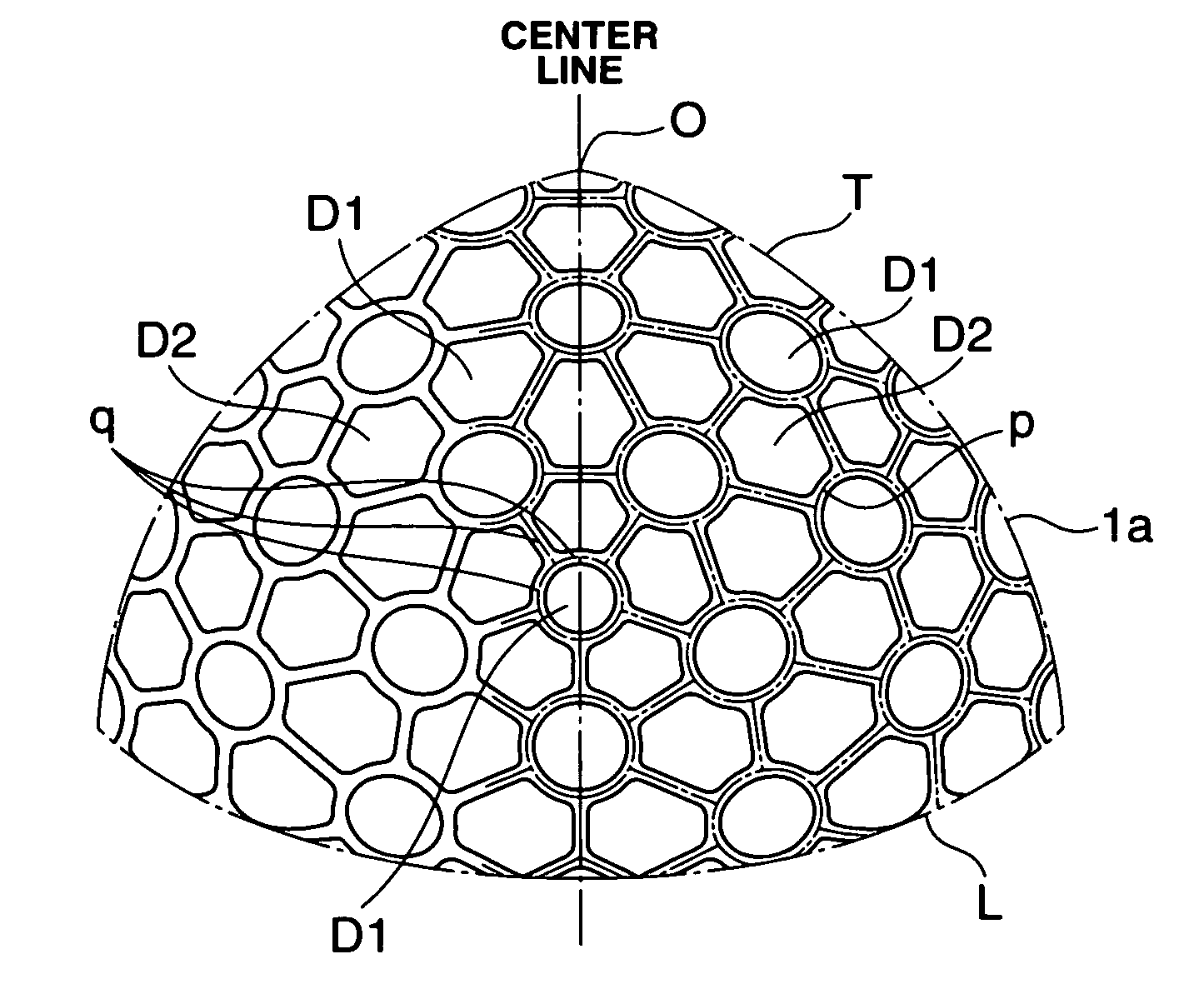
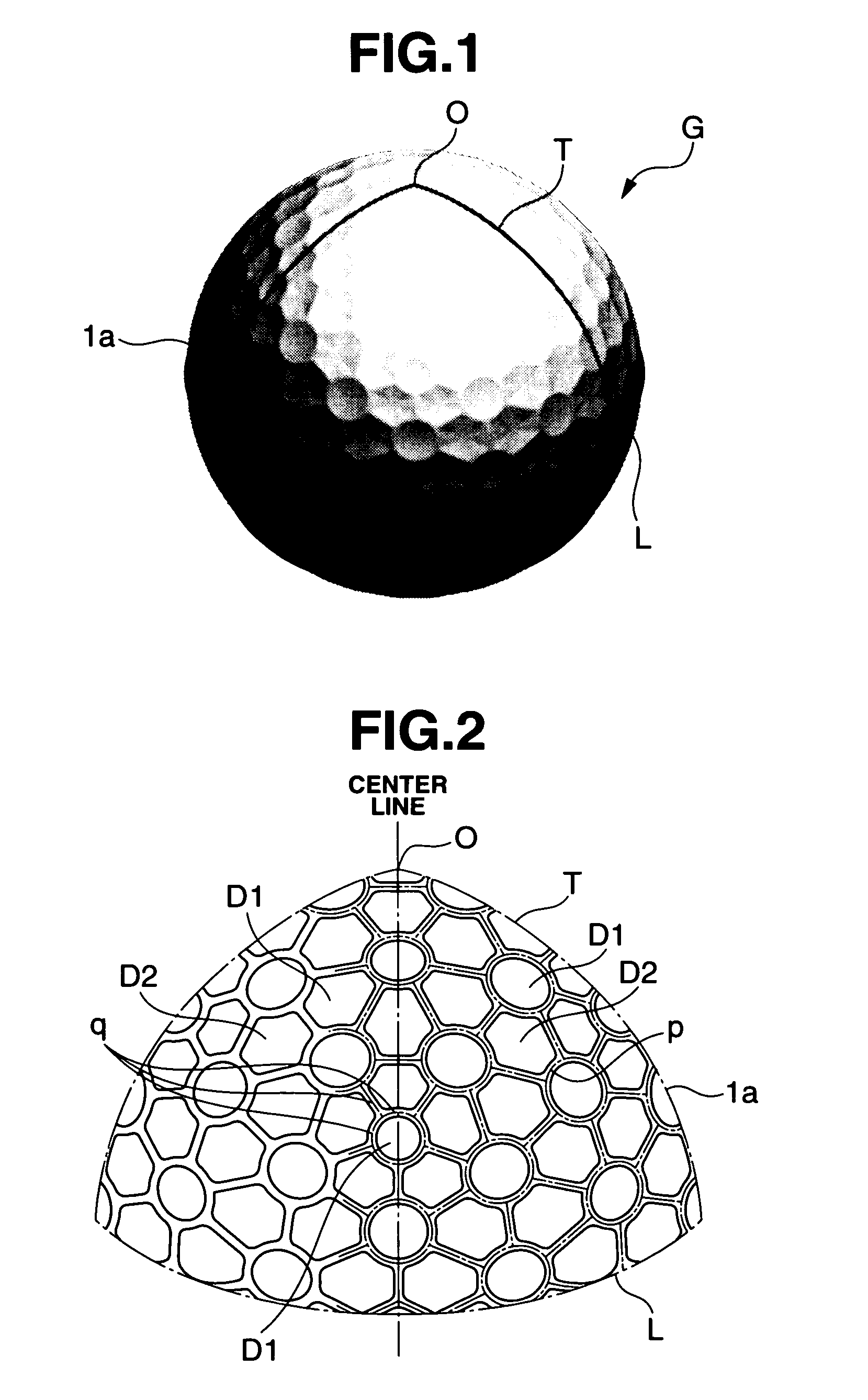
[0040] The invention will be described with reference to the following Examples and Comparative Examples, which are not intended to restrict the scope of the invention. Example 1 and Comparative Examples 1 and 2 Golf ball samples were prepared, each having dimples arranged as shown in FIG. 1 (Example 1), FIG. 6 (Comparative Example 1), and FIG. 7 (Comparative Example 2). They were tested for flight performance. Dimples are arranged on the spherical surface divided into six sectors (in Example 1 and Comparative Example 1) or icosahedron (in Comparative Example 2).

[0041] The golf ball samples in these examples are of three-piece structure consisting of a core (1), a cover (3), and an intermediate layer (2), as shown in FIG. 5. The details of each constituent are given below.

Core

[0042] The core was formed from a rubber composition composed of the following components. [0043] Polybutadiene (100 pbw), “BR01” from JSR. [0044] Zinc acrylate (25 pbw). [0045] Dicumyl peroxide (0.8 pbw), ...


PUM


Abstract

Disclosed herein is a golf ball having on its surface a number of dimples and a number of edges separating dimples from each other, wherein the edges are formed from a plurality of edge elements joined together such that some of the joining parts of the edge elements assume a smoothly curved shape as viewed from above. The golf ball has improved aerodynamic performance due to dimples and achieves a long flying distance.

Description

BACKGROUND OF THE INVENTION [0001] The present invention relates to a golf ball which excels in flight performance. [0002] For a golf ball to fly over a long distance, it should have a high rebound resilience and a low aerodynamic resistance attributable to dimples arranged on its surface. For the purpose of reducing aerodynamic resistance, there have been proposed several methods for arranging dimples on the ball surface as densely and uniformly as possible. [0003]FIG. 7 illustrates a golf ball (G) with dimples (s) arranged in an ordinary manner. Each dimple is a circular dent as viewed from above. If such circular dimples (s) are to be densely arranged, it is necessary to narrow down the flat part or land (t) separating adjoining dimples from each other. Even though the flat part (t) is infinitely narrow, there still exists a triangular or rectangular flat part of certain size in the area surrounded by three or four dimples. On the other hand, it is essential to arrange dimples as...

Claims


Application Information

Patent Timeline
Patent Type & Authority Applications(United States)
IPC IPC(8): A63B37/12
CPCA63B37/0004A63B37/0007A63B37/0012A63B37/0084A63B37/0018A63B37/0075A63B37/0017
Inventor SATO, KATSUNORIKASASHIMA, ATSUKI
Owner BRIDGESTONE SPORTS
Why Eureka
Try Eureka