Devices, systems, and methods for retaining a native heart valve leaflet
What is Al technical title?
Al technical title is built by PatSnap Al team. It summarizes the technical point description of the patent document.
a heart valve and leaflet technology, applied in the field of devices, systems and methods for improving the function of the heart valve, can solve problems such as flailed leaflets, valve malfunction, chords becoming stretched,
Inactive Publication Date: 2006-03-30
VENTURE LENDING & LEASING IV
View PDF73 Cites 123 Cited by
Summary
Abstract
Description
Claims
Application Information
AI Technical Summary
This helps you quickly interpret patents by identifying the three key elements:
Problems solved by technology
Method used
Benefits of technology
[0018] Although mild cases of mitral valve regurgitation result in few problems, more severe and chronic cases eventually weaken the heart a
Problems solved by technology
Valve malfunction can result from the chords becoming stretched, and in some cases tearing.
When a chord tears, the result is a flailed leaflet.
Also, a normally structured valve may not function properly because of an enlargement of the valve annulus pulling the leaflets apart.
This condition is referred to as a dilation of the annulus and generally results from heart muscle failure.
In addition, the valve may be defective at birth or because of an acquired disease, usually infectious or inflammatory.
As a result, the leaflets do not form a tight seal, and blood is regurgitated into the atrium.
During subsequent ventric
Method used
Image
Click on the blue label to locate the original text in one second.
Reading with bidirectional positioning of images and text.
Examples
Embodiment Construction
[0047] Although the disclosure hereof is detailed and exact to enable those skilled in the art to practice the invention, the physical embodiments herein disclosed merely exemplify the invention, which may be embodied in other specific structure. While the preferred embodiment has been described, the details may be changed without departing from the invention, which is defined by the claims.
[0048] I. Implants for Retaining a Native Heart Valve Implant
[0049] A. Planar Wire-Form Implants
[0050] 1. Overview
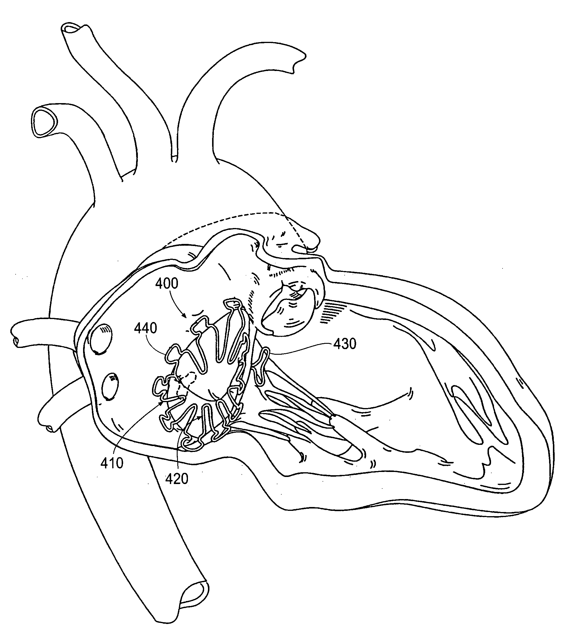
[0051]FIGS. 4, 5, and 6 show an implant 400 sized and configured to retain at least one dysfunctional native heart valve leaflet. In use (see, in particular, FIG. 4), the implant 400 rests adjacent all or a portion of the native heart valve annulus, which, in FIG. 4, is in the atrium. The implant 400 includes a scaffold 410, at least a portion of which defines a pseudo-annulus. The scaffold 410 includes a retaining element 420 at or near the pseudo-annulus. The retaining element 4...
PUM
Abstract
Devices, systems and methods retain a native heart valve leaflet to prevent retrograde flow. The devices, systems, and methods employ an implant that, in use, rests adjacent a valve annulus and includes a retaining structure that is sized and shaped to overlay at least a portion of one or more native valve leaflets. The retaining structure retains the leaflet or leaflets it overlays, to resist leaflet eversion and/or prolapse. In this way, the implant prevents or reduces regurgitation. The implant does not interfere significantly with the opening of and blood flow through the leaflets during periods of antegrade flow.
Description
RELATED APPLICATIONS [0001] This application claims the benefit of co-pending U.S. patent application Ser. No. 09 / 666,617, filed Sep. 20, 2000 and entitled “Heart Valve Annulus Device and Methods of Using Same,” which is incorporated herein by reference. This application also claims the benefit of Patent Cooperation Treaty Application Serial No. PCT / US 02 / 31376, filed Oct. 1, 2002 and entitled “Systems and Devices for Heart Valve Treatments,” which claimed the benefit of U.S. Provisional Patent Application Serial No. 60 / 326,590, filed Oct. 1, 2001, which are incorporated herein by reference. This application also claims the benefit of U.S. Provisional Application Serial No. 60 / 429,444, filed Nov. 26, 2002, and entitled “Heart Valve Remodeling Devices;” U.S. Provisional Patent Application Serial No. 60 / 429,709, filed Nov. 26, 2002, and entitled “Neo-Leaflet Medical Devices;” and U.S. Provisional Patent Application Serial No. 60 / 429,462, filed Nov. 26, 2002, and entitled “Heart Valve ...
Claims
Application Information
Patent Timeline
Application Date:The date an application was filed.
Publication Date:The date a patent or application was officially published.
First Publication Date:The earliest publication date of a patent with the same application number.
Issue Date:Publication date of the patent grant document.
PCT Entry Date:The Entry date of PCT National Phase.
Estimated Expiry Date:The statutory expiry date of a patent right according to the Patent Law, and it is the longest term of protection that the patent right can achieve without the termination of the patent right due to other reasons(Term extension factor has been taken into account ).
Invalid Date:Actual expiry date is based on effective date or publication date of legal transaction data of invalid patent.
IPC IPC(8): A61F2/24A61F
CPCA61F2/2454
Inventor RAHDERT, DAVID A.MACOVIAK, JOHN A.MACHOLD, TIMOTHY R.CHANG, ROBERT T.SOSS, RICK A.