Coupled parametric design of flow control and duct shape

a flow control and duct design technology, applied in the direction of cad techniques, machines/engines, instruments, etc., can solve the problems of engine stall, pressure loss, inlet and nozzle length of such applications, etc., to reduce length, improve flow quality, and reduce offset

Inactive Publication Date: 2006-03-30
RAYTHEON TECH CORP +1
View PDF5 Cites 25 Cited by
  • Summary
  • Abstract
  • Description
  • Claims
  • Application Information

AI Technical Summary

Benefits of technology

[0012] The present invention provides a novel approach to the design of ducts for applications such as inter-turbine transition ducts, serpentine-ducts, inlets and diffusers, although persons of skill in the art will appreciate the applicability to other, similar gas turbine engine duct components. The design of the shape of the duct is coupled with parameterized flow control enabling the design of higher performance ducts with reduced length, larger offsets and / or improved flow quality (reduced flow distortion). The approach of the present invention is of general applicability to any duct or diffuser-like flow device, is best suited for subsonic flows, and can be used with both passive and active, steady and unsteady flow control schemes.
[0013] Some of the individual steps of the methodology of the present invention are not new in themselves. In fact, parametric geometries for aerodynamic design or flow control to improve flow characteristics have both been used extensively. However the coupling of the aerodynamic duct design with the design of the flow control is novel and can yield significant benefits.

Problems solved by technology

The inlet and nozzle for such applications may be significantly long to minimize pressure losses.
In addition, longer inlets may be required to reduce pressure distortions that could cause the engine to stall.
The length of the inlet and / or nozzle may lead to undesired weight increase and, in the cases of some unmanned configurations, may become a limiting factor for the entire vehicle size.

Method used


Image

  • Coupled parametric design of flow control and duct shape
  • Coupled parametric design of flow control and duct shape
  • Coupled parametric design of flow control and duct shape

Examples


Embodiment Construction

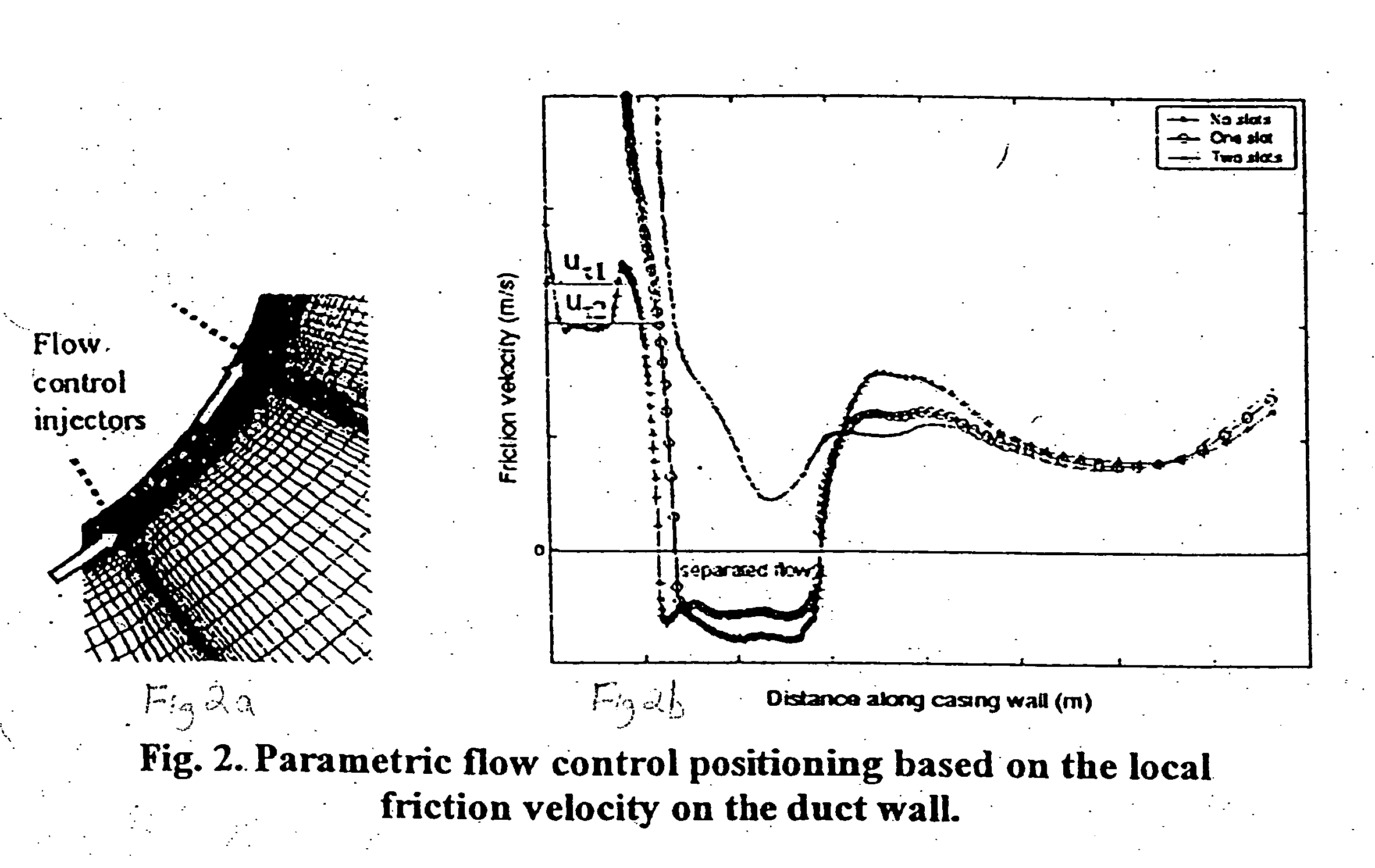
[0016] As noted above, the overall process of the invention includes the step 20 of parametrically defining the geometry of the duct wall shape, the step 40 of parametrically defining one or more flow control actuators in the duct wall and associating the actuator position to the local flow characteristics, the step60 of measuring a plurality of performance parameters or metrics (e.g., flow characteristics) of the duct and comparing the results of the measurement with desired or target parameters; and the step 80 of selecting the optimal duct geometry and flow control for at least a portion of the duct. Each of the steps of the claimed inventions, as reflected in various preferred embodiments of the present invention, is discussed in the examples set forth below.

[0017] A. Duct Geometry Parameterization

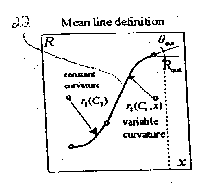
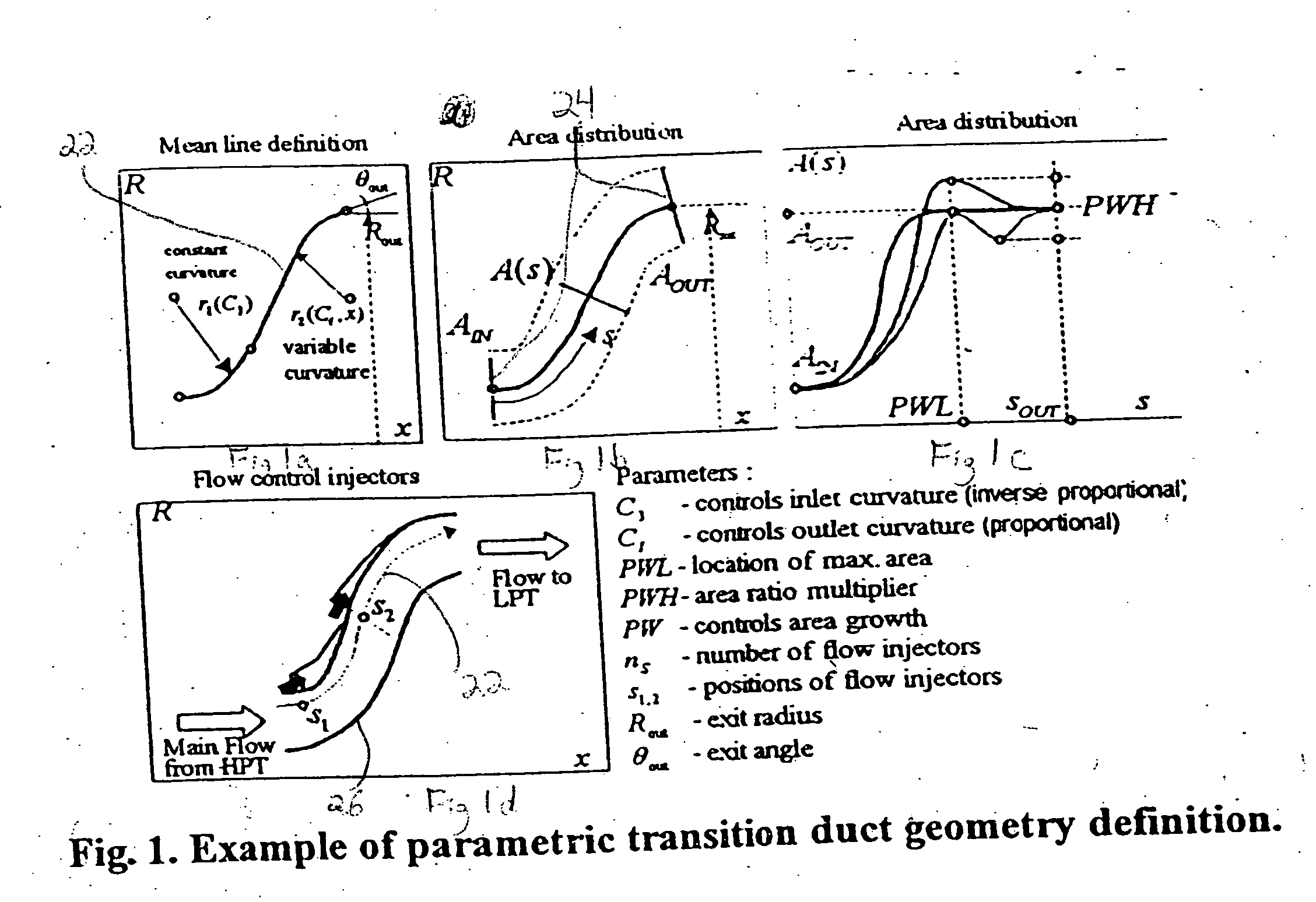
[0018] The duct geometry parameterization step 20 as reflected in a first preferred embodiment as applied to the design of an interturbine transition duct, is shown in FIGS. 1a-1d. I...


PUM


Abstract

A method for designing gas turbine engine components using a coupled parametric analysis of part geometry and flow control is disclosed. Included are the steps of parametrically defining the geometry of the duct wall shape, parametrically defining one or more flow control actuators in the duct wall, measuring a plurality of performance parameters or metrics (e.g., flow characteristics) of the duct and comparing the results of the measurement with desired or target parameters, and selecting the optimal duct geometry and flow control for at least a portion of the duct, the selection process including evaluating the plurality of performance metrics in a pareto analysis. The use of this method in the design of inter-turbine transition ducts, serpentine ducts, inlets, diffusers, and similar components provides a design which reduces pressure losses and flow profile distortions.

Description

CROSS REFERENCE TO RELATED APPLICATIONS [0001] Some of the subject matter disclosed herein is related to the subject matter of commonly owned U.S. patent applications and patents: Ser. No. 09 / 212,923, filed on Dec. 16, 1998, now abandoned, entitled “Method of Creating a Parametric Model in a CAD System”; U.S. Pat. No. 6,587,741, issued Jul. 1, 2003, entitled “Method and System for Designing a Spline Coupling”; U.S. Pat. No. 6,393,331, issued on May 21, 2002, entitled “Method of Designing a Turbine Blade Outer Air Seal”; Ser. No. 09 / 511,549, filed on Feb. 23, 2000, entitled “Method and System for Designing a Low Pressure Turbine Shaft”; and Ser. No. 09 / 608,620, filed on Jun. 30, 2000, entitled “Method and System for Designing Frames and Cases”. All of the foregoing patent applications and patents are hereby incorporated by reference.GOVERNMENT INTEREST [0002] The Government has rights in this invention, pursuant to NASA Contract No. NAS3-98005.I. FIELD OF THE INVENTION [0003] The fie...

Claims


Application Information

Patent Timeline
Patent Type & Authority Applications(United States)
IPC IPC(8): G06F17/50
CPCF01D5/145F01D9/023F01D17/105F01D25/305Y02T50/675F05D2270/17G06F17/5009G06F2217/16Y02T50/673F02C9/18G06F2111/10G06F30/20Y02T50/60
Inventor FLOREA, RAZVANBERTUCCIOLI, LUCA
Owner RAYTHEON TECH CORP
Why Eureka
Try Eureka