Acoustic foam sound reducer for vacuum power unit

a technology of vacuum power units and acoustic foam, which is applied in the direction of auxillary pretreatment, separation process, filtration separation, etc., can solve the problems of annoying users and large size of the motor required to generate the desired amount of vacuum, and achieve the effect of increasing the effect of dampening the amount of sound

Active Publication Date: 2006-04-06
H P PROD
View PDF31 Cites 4 Cited by
  • Summary
  • Abstract
  • Description
  • Claims
  • Application Information

AI Technical Summary

Benefits of technology

[0007] One aspect of the present invention is to provide an improved power unit for a vacuum cleaning system having a unique sound reducer mounted therein which increases the

Problems solved by technology

One problem with these types of systems is that the size of the motor required to generate the desir

Method used


Image

  • Acoustic foam sound reducer for vacuum power unit
  • Acoustic foam sound reducer for vacuum power unit
  • Acoustic foam sound reducer for vacuum power unit

Examples


first embodiment

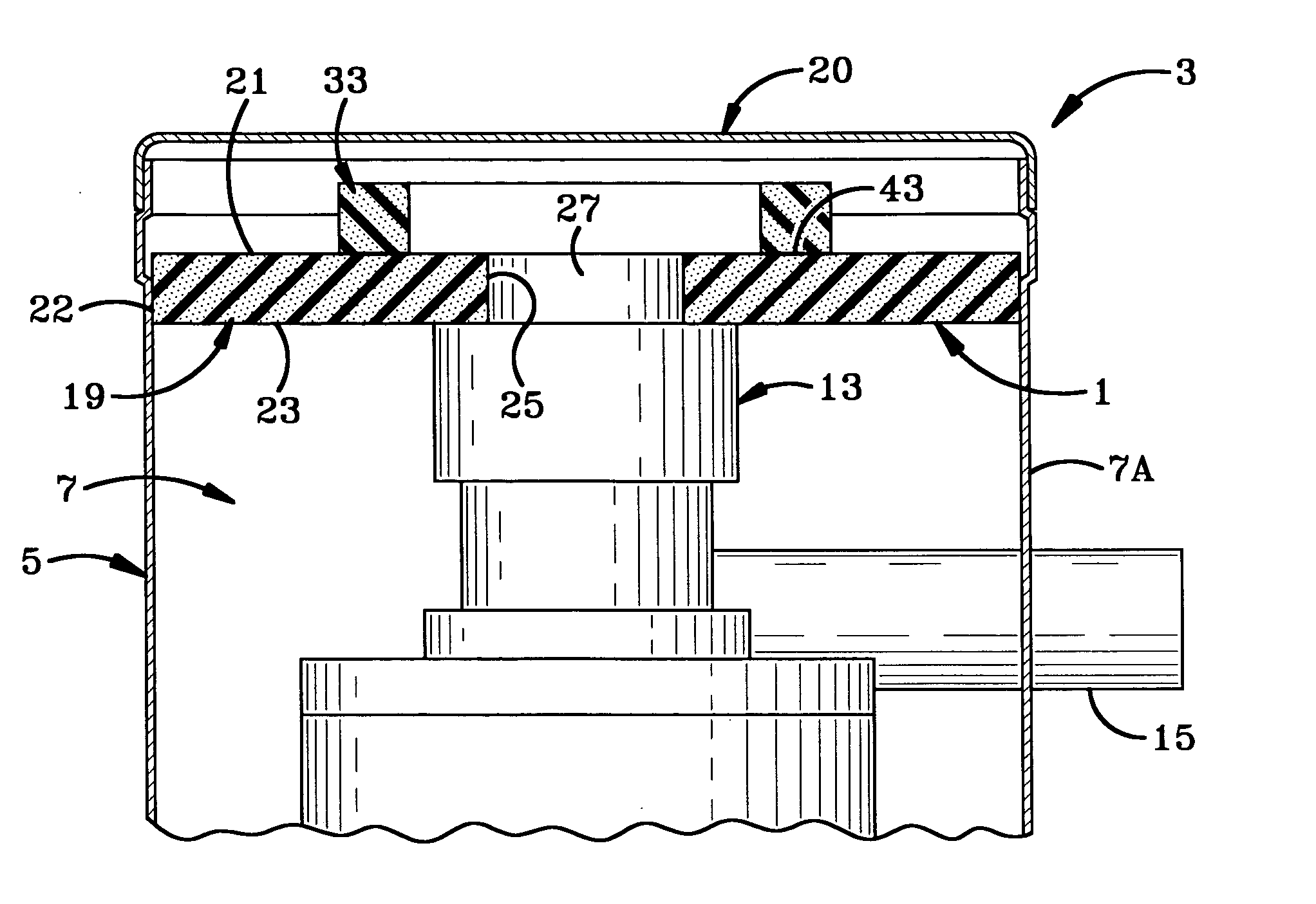
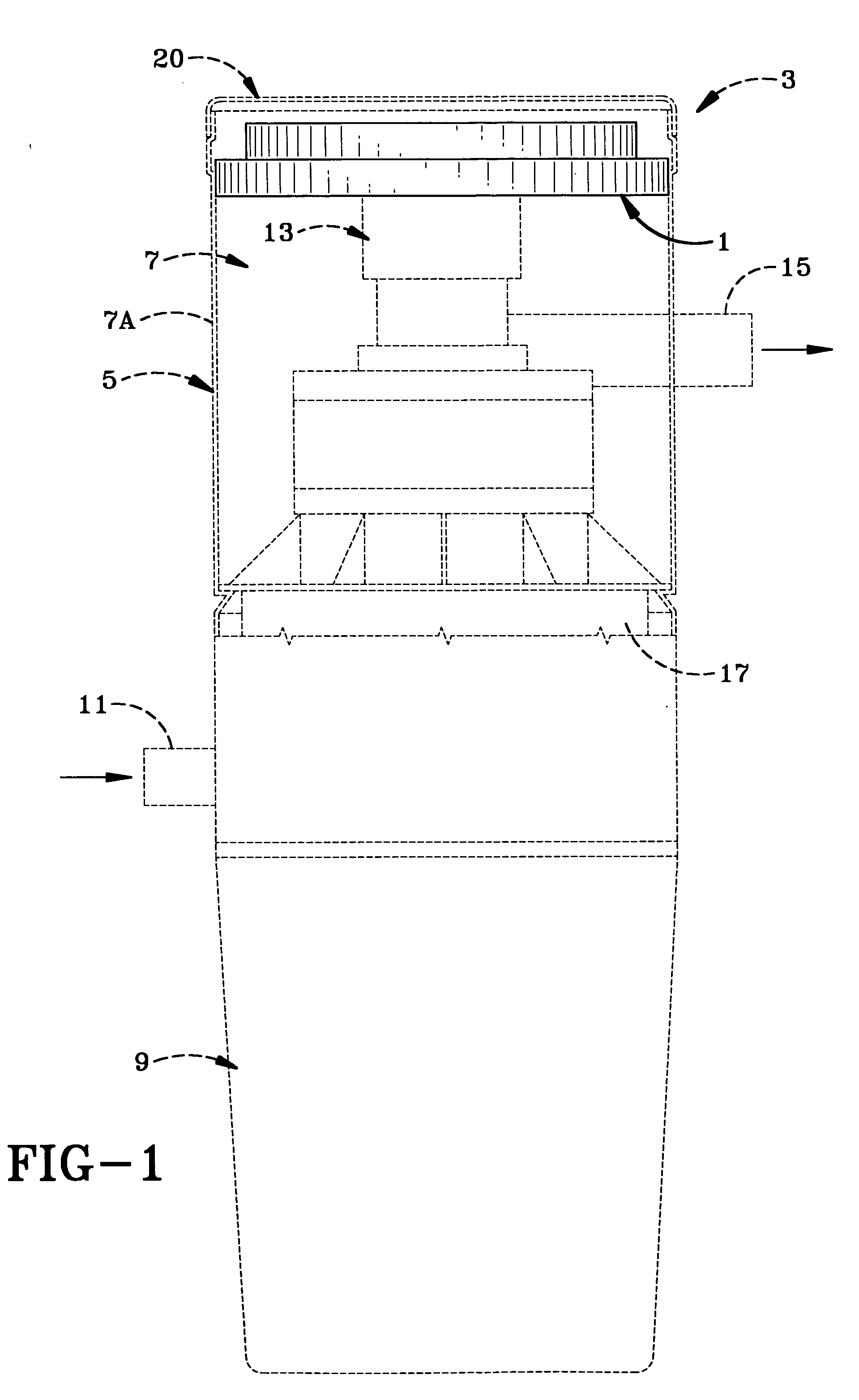
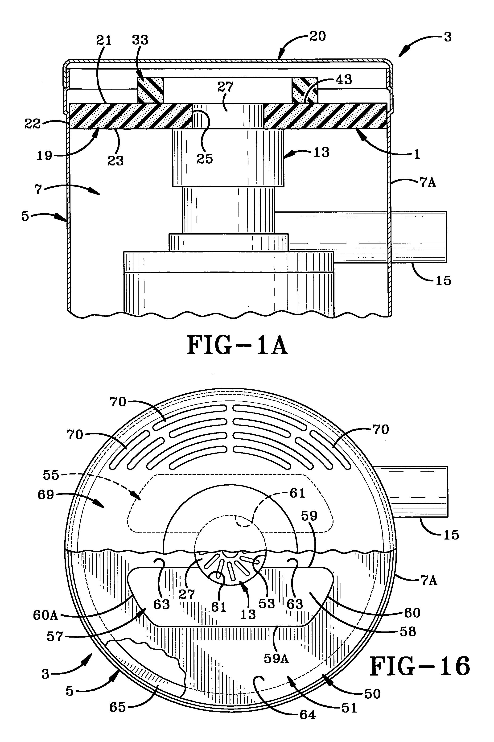
[0036] the improved sound reducer and power unit containing the same is shown in FIG. 1. The sound reducer is indicated generally at 1 and is shown in full lines with the vacuum cleaning unit shown in dot dashed lines, and indicated generally at 3. Vacuum cleaning power unit 3 is of a construction well-known in the art and consists of a main canister indicated generally at 5, having an annular configuration and formed with an upper motor compartment 7 and a lower debris collection compartment 9. Some type of filtering mechanism (not shown), such as a cyclonic unit or filter medium will be mounted between motor compartment 7 and debris compartment 9 to filter out the dust, dirt and other debris which enters debris compartment 9 through an intake line 11. Line 11 communicates with the various outlets spaced throughout the building in which a cleaning wand will be attached.

[0037] A vacuum producing motor 13 is mounted in motor compartment 7 and usually communicates with an exhaust tube...

third embodiment

[0044] the improved sound reducer is indicated generally at 75, and is shown in FIGS. 17-19. Sound reducer 75 is very similar to the construction of sound reducer 1 in that it includes an annular base member 76 and a pair of arcuate-shaped partitions 77 and 78. Outer partition 78 is very similar to partition 31 of sound reducer 1 having an arcuate length of between 150° and 170° with the preferred length being 160°. Arcuate partition 77 has a shorter arcuate length of between 130° and 150° with the preferred arcuate length being 140°. Also, as can be seen in FIG. 17, partition 77 has a shorter height than that of partition 78. For example, partition 77 has a height of one inch and partition 78 has a height of one and one-half inches. This enables the air to flow through the various sound and cooling passages from motor portion 27 and through passages 80 and 81 and over top surface 82 of partition 77 to vent openings 83 formed in canister lid 85. These passages also provide the irreg...


PUM

PropertyMeasurementUnit
Angleaaaaaaaaaa
Angleaaaaaaaaaa
Angleaaaaaaaaaa

Abstract

A power unit for an in-wall vacuum cleaning system has a first compartment which contains a motor for producing a vacuum at remote wand receptacles and a second compartment for separating and collecting the debris. An improved sound reducer is mounted in the motor compartment for reducing the sound level emitted by the motor and providing good cooling airflow for the motor. The sound reducer includes a disc-shaped base having a central opening for receiving a portion of the motor and a pair of partitions mounted on the base and forming a plurality of irregularly-shaped sound passages for breaking up the sound waves traveling therethrough. The base and partitions are formed of an acoustic foam which assist in absorbing the sound waves.

Description

CROSS REFERENCE TO RELATED APPLICATIONS [0001] This application is a continuation-in-part of pending U.S. Ser. No. 29 / 205,218, filed May 11, 2004.BACKGROUND OF THE INVENTION [0002] 1. Technical Field [0003] The invention relates to built-in vacuum cleaning systems in which a power unit containing a motor and a debris collection system is connected to various wall outlets through piping extending throughout the building. More particularly, the invention relates to such a power unit and to a sound reducer mounted in the unit to enhance the cooling and reduce the sound of the vacuum supplying motor mounted in the unit. [0004] 2. Background Information [0005] Built-in vacuum cleaning systems are well-known in the building and cleaning industry and consists of a main power unit usually mounted in the basement or a garage for proper air circulation. The power unit contains a motor and a debris collection receptacle with various filters. When the motor is turned on, it creates a suction or...

Claims


Application Information

Patent Timeline
IPC IPC(8): F01N3/06
CPCA47L5/38A47L9/0081A47L9/22
Inventor NIESCHWITZ, DARRELL V.GABRIC, ANDREW L.
Owner H P PROD
Why Eureka
Try Eureka