Multi-head tab bonding tool

Inactive Publication Date: 2006-04-06
REIBER STEVEN F
View PDF81 Cites 2 Cited by
  • Summary
  • Abstract
  • Description
  • Claims
  • Application Information

AI Technical Summary

Benefits of technology

[0018] The present invention advantageously provides for the use of multi-head TAB bonding tools to accelerate the TAB bonding process whereby an operator may complete an assembly process through the use of one or two bonds instead of the usual four.

Problems solved by technology

Single-point bonding is a more time-consuming process than gang bonding.
Prior art bonding tool tips, including those made of aluminum oxide or tungsten carbide—lack the sufficient hardness to prevent deformation under pressure and mechanical durability so that many bonds can be made before replacement.

Method used


Image

  • Multi-head tab bonding tool
  • Multi-head tab bonding tool
  • Multi-head tab bonding tool

Examples


Embodiment Construction

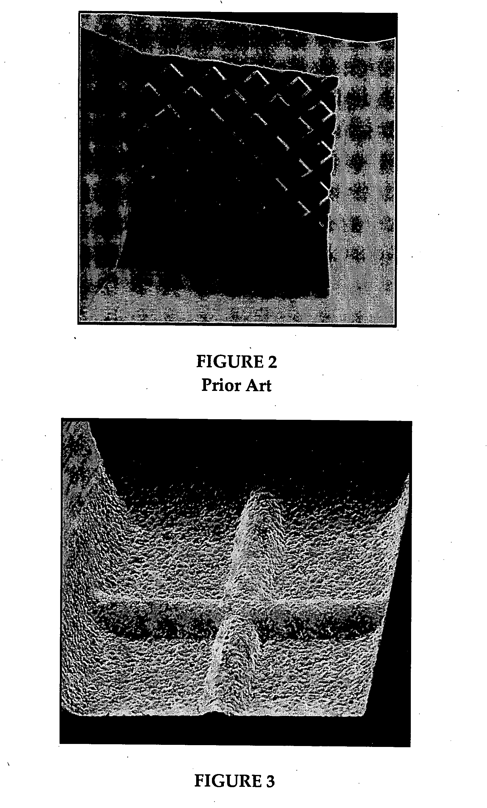
[0029]FIG. 3 illustrates a single point TAB tool utilizing a double cross groove according to an embodiment of the present invention and as may be utilized in a multi-head TAB bonding tool. Reference to a double cross groove is not meant to limit the scope of the present TAB tool in that other groove configurations may be utilized. These configurations include, but are not limiting to, a single cross groove, a single point, a protruding ‘V,’ and the aforementioned waffle tool.

[0030] An exemplary TAB tool as illustrated in FIG. 3 may be one-half inch (12-13 mm) long and approximately one-sixteenth inch (1.6 mm) in diameter. The bonding tool tip itself is usually a 3 to 10 mils (0.08 to 0.25 mm) square. A two-headed bonding tool may exhibit similar characteristics in that an exemplary two-headed bonding tool may be approximately one-half inch (12-13 mm) long and about one-sixteenth inch (1.6 mm) in diameter. The bonding tool tips may be from 3 to 10 mils (0.08 to 0.25 mm) by 20 to 26...


PUM


Abstract

A bonding tool for use in multi-head tape automated bonding (TAB) is provided. The bonding tool comprises a plurality of TAB bonding heads, the TAB bonding heads providing for electrical dissipation wherein current flow is low enough so as not to damage a device being bonded and high enough to avoid the build up of a charge that may discharge to the device being bonded.

Description

CROSS-REFERENCE TO RELATED APPLICATIONS [0001] The present application claims the priority benefit of U.S. provisional patent application No. 60 / 610,847 (2834PRV) filed Sep. 17, 2004 and entitled “Multi-Head TAB Bonding Tool”; the present application is also a continuation-in-part and claims the priority benefit of U.S. patent application Ser. No. 11 / 107,308 (3100US) filed Apr. 15, 2005 and entitled “Flip Chip Bonding Tool and Ball Placement Capillary”; U.S. patent application Ser. No. 11 / 107,308 (3100US) is a continuation-in-part and claims the priority benefit of U.S. patent application Ser. No. 10 / 942,311 (2617US) filed Sep. 15, 2004 and entitled “Flip Chip Bonding Tool Tip”; U.S. patent application Ser. No. 11 / 107,308 (3100US) is also a continuation-in-part and claims the priority benefit of U.S. patent application Ser. No. 10 / 943,151 (2835US) filed Sep. 15, 2004 and entitled “Bonding Tool with Resistance”; U.S. patent application Ser. Nos. 10 / 942,311 (2617US) and 10 / 943,151 (28...

Claims


Application Information

Patent Timeline
IPC IPC(8): B23K37/00
CPCB23K3/0307B23K2201/40B23K2101/40
Inventor REIBER, STEVEN F.
Owner REIBER STEVEN F
Why Eureka
Try Eureka