Hydraulic park pawl brake system

Inactive Publication Date: 2006-04-06
HAYES BRAKE
View PDF13 Cites 22 Cited by
  • Summary
  • Abstract
  • Description
  • Claims
  • Application Information

AI Technical Summary

Benefits of technology

[0006] Additional benefits would accrue from such a solution that could be implemented on a low-cost basis and without the need for additional separate hydraulic ac

Problems solved by technology

The problem with this method is that when there is a change in temperature, the brake fluid expands or contracts (according to whether the temperature increases or decreases, respectively) thus changing the pressure in the brake system, and consequently, the brake torque exerted by the brake caliper.
This is an issue, since there can be reduction in pressure such that there is insufficient brake torque to hold the vehicle in place (as on a grade).
Conversely, when the pressure increases due to increase in temperature, th

Method used


Image

  • Hydraulic park pawl brake system
  • Hydraulic park pawl brake system
  • Hydraulic park pawl brake system

Examples


Embodiment Construction

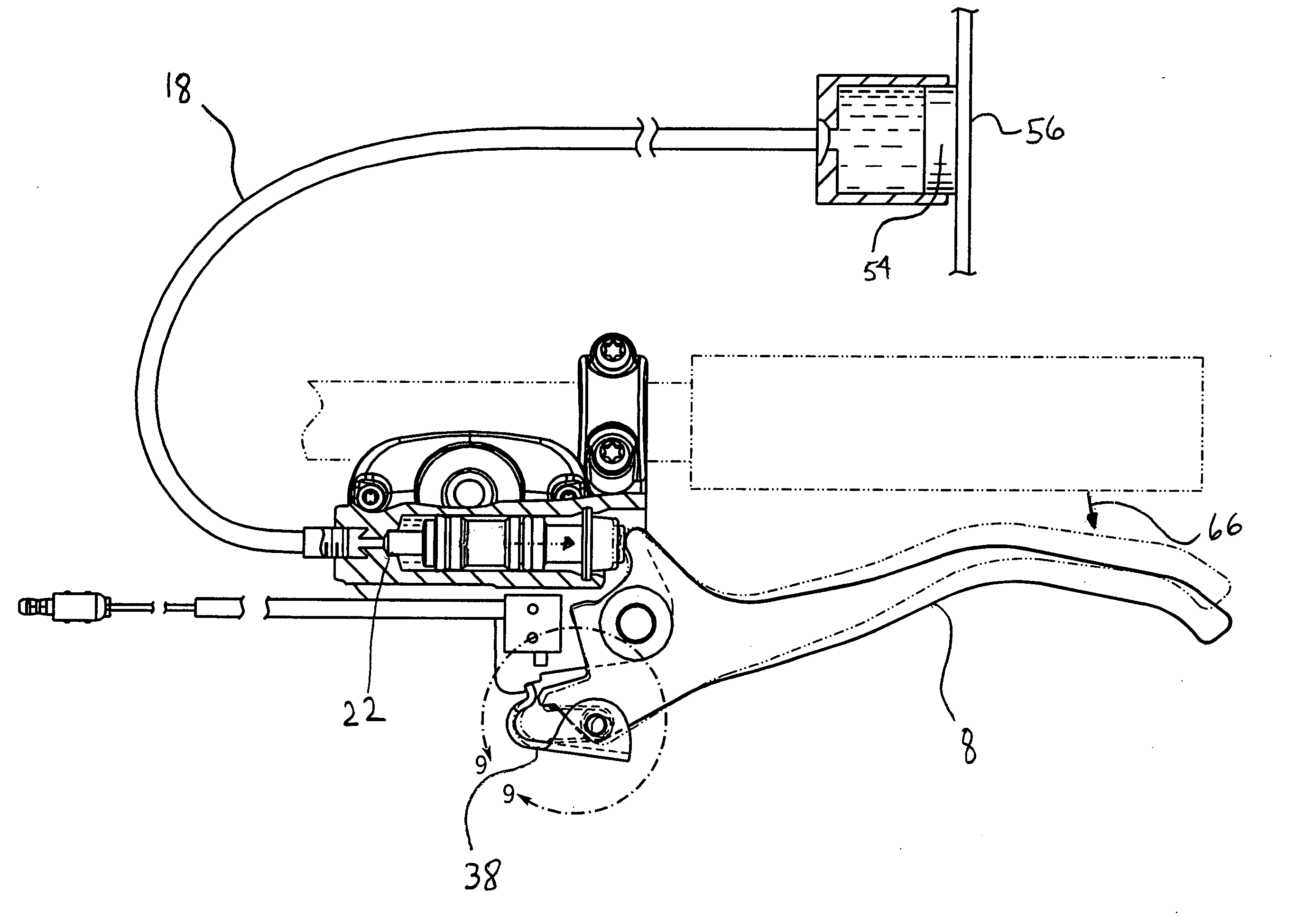
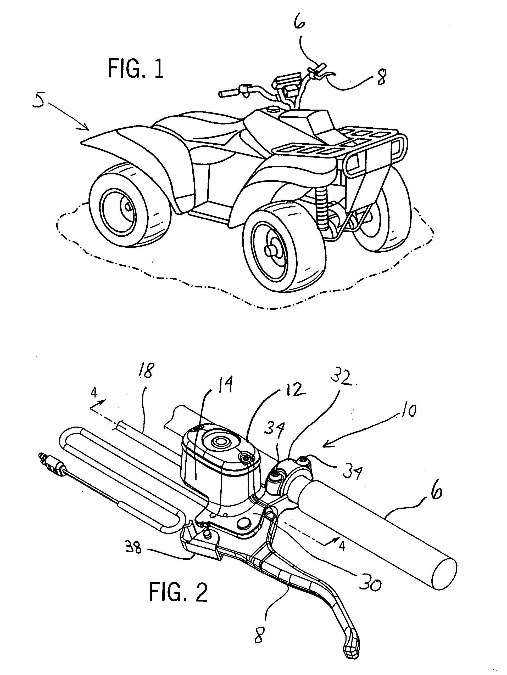
[0018]FIG. 1 is a perspective view of a vehicle for use with the present invention and FIG. 2 is a perspective view of a hand operated hydraulic brake system for use with the vehicle of FIG. 1. Referring to FIGS. 1-2, a vehicle 5 is shown for use with the present invention. Although a specific vehicle is shown as an all terrain vehicle (ATV), other types of vehicles, including snowmobiles or other powersports or off-road vehicles, are contemplated for use with the present invention. The present invention is used in a handbrake portion of vehicle 5 used for maintaining the vehicle 5 in a parked capacity, also called a park brake that includes a grip handle 6 used with brake lever 8 and against which hand pressure is applied to force the brake lever 8 towards the handle 6 in a generally known manner to stop vehicle 5. A left side vehicle handbrake is shown.

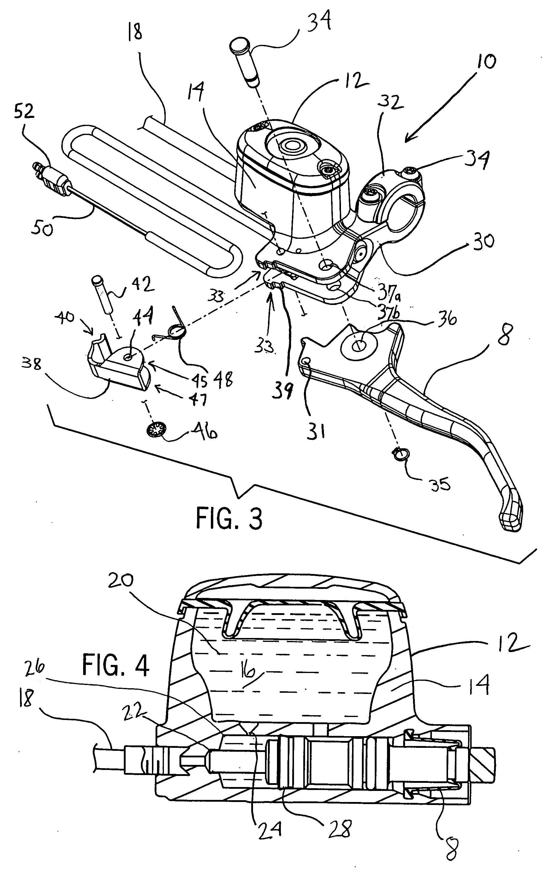
[0019] A hand operated hydraulic brake assembly 10 used with a vehicle such as vehicle 5 is shown in more detail in FIGS. 2-4. It...


PUM


Abstract

A handle bar master cylinder assembly for supplying pressurized hydraulic fluid through a brake line to actuate a brake in a vehicle. The assembly comprises a master cylinder having a master cylinder body defining a hydraulic fluid reservoir, a reciprocating master cylinder piston located within a hydraulic fluid reservoir, a handle bar attachment bracket connected to the master cylinder body and having a park pawl engagement section, a hand brake lever rotatably secured to the handle bar attachment bracket and in abutting contact with the reciprocating master cylinder piston, and a park pawl pivotably secured to the hand brake lever, the park pawl having an end engageable with the park pawl engagement section of the handle bar attachment bracket to maintain the brake lever in an applied position. When the pawl is set, a park pawl compensation flexure occurs due to a change in hydraulic fluid temperature.

Description

BACKGROUND AND SUMMARY OF THE INVENTION [0001] The present invention relates generally to hydraulically held park brake systems, and more specifically, to a park pawl accumulator (PPA) for a service brake as part of a hydraulic brake system. [0002] Typical hydraulic brake systems in applications such as ATV and snowmobile use a hydraulically held park brake. The service brake has a lever that the operator moves to apply pressure hydraulically to the brake caliper(s). The hydraulically held park brake operates by locking the service brake lever in the applied position. Typically this is accomplished by use of a pawl that is connected to the service brake lever that engages into the body of the master cylinder in such a way that the service brake lever remains in the position to which it was moved by the operator. The problem with this method is that when there is a change in temperature, the brake fluid expands or contracts (according to whether the temperature increases or decreases...

Claims


Application Information

Patent Timeline
IPC IPC(8): B60T17/16
CPCB60T7/10B60T11/22B62L3/023B62L3/06
Inventor LICHTENSTEIGER, TOBYSCHLINTZ, JOHN
Owner HAYES BRAKE
Why Eureka
Try Eureka