Flurescent lamp and luminaire

a technology of fluorescent lamps and luminaires, which is applied in the direction of discharge tubes, low-pressure discharge lamps, discharge tubes luminescnet screens, etc., can solve the problems of easy cracking or flaking of the protection layer or the phosphor layer, damage such as cracking may easily occur on the connection portion b>324/b> or in the vicinity, and achieves excellent luminous efficiency, small bulb strain, and high strength

Inactive Publication Date: 2006-04-06
TOSHIBA LIGHTING & TECH CORP
View PDF12 Cites 8 Cited by
  • Summary
  • Abstract
  • Description
  • Claims
  • Application Information

AI Technical Summary

Benefits of technology

[0011] An object of the present invention, which was made in view of the above-described circumstances encountered in the prior art, is therefore to provide a fluorescent lamp and a lighting apparatus, which have a small strain in bulb, a high strength and an excellent luminous efficiency.

Problems solved by technology

Accordingly, there is a problem that fissure, flaking off or crack may easily occur on the protection layer or the phosphor layer.
However, it is not always easy to carry out the formation process of the connection portion 324, and the strength of the connection portion 324 is apt to be deteriorated, thus causing problems.
As a result, damage such as crack may easily occur on the connection portion 324 or in the vicinity thereof.
This leads to a decreased length of the discharge paths of the bulbs 322, 323, thus deteriorating the luminous efficiency.
Therefore, it is not easy to carry out the coupling operation due to difference in radius of curvature between the opposing circumferential surfaces of the bulbs, thus causing problems.

Method used


Image

  • Flurescent lamp and luminaire
  • Flurescent lamp and luminaire
  • Flurescent lamp and luminaire

Examples


first embodiment

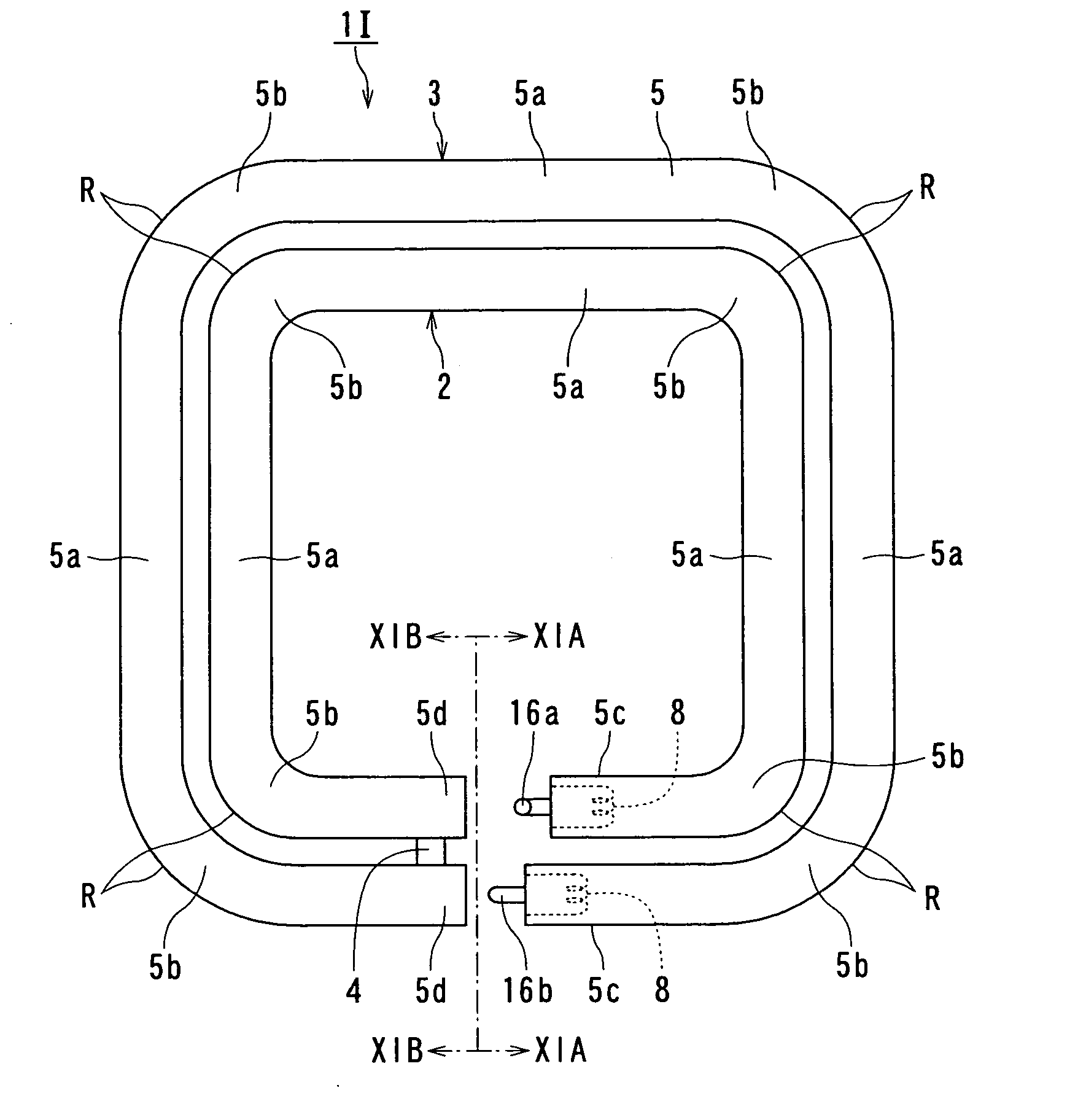
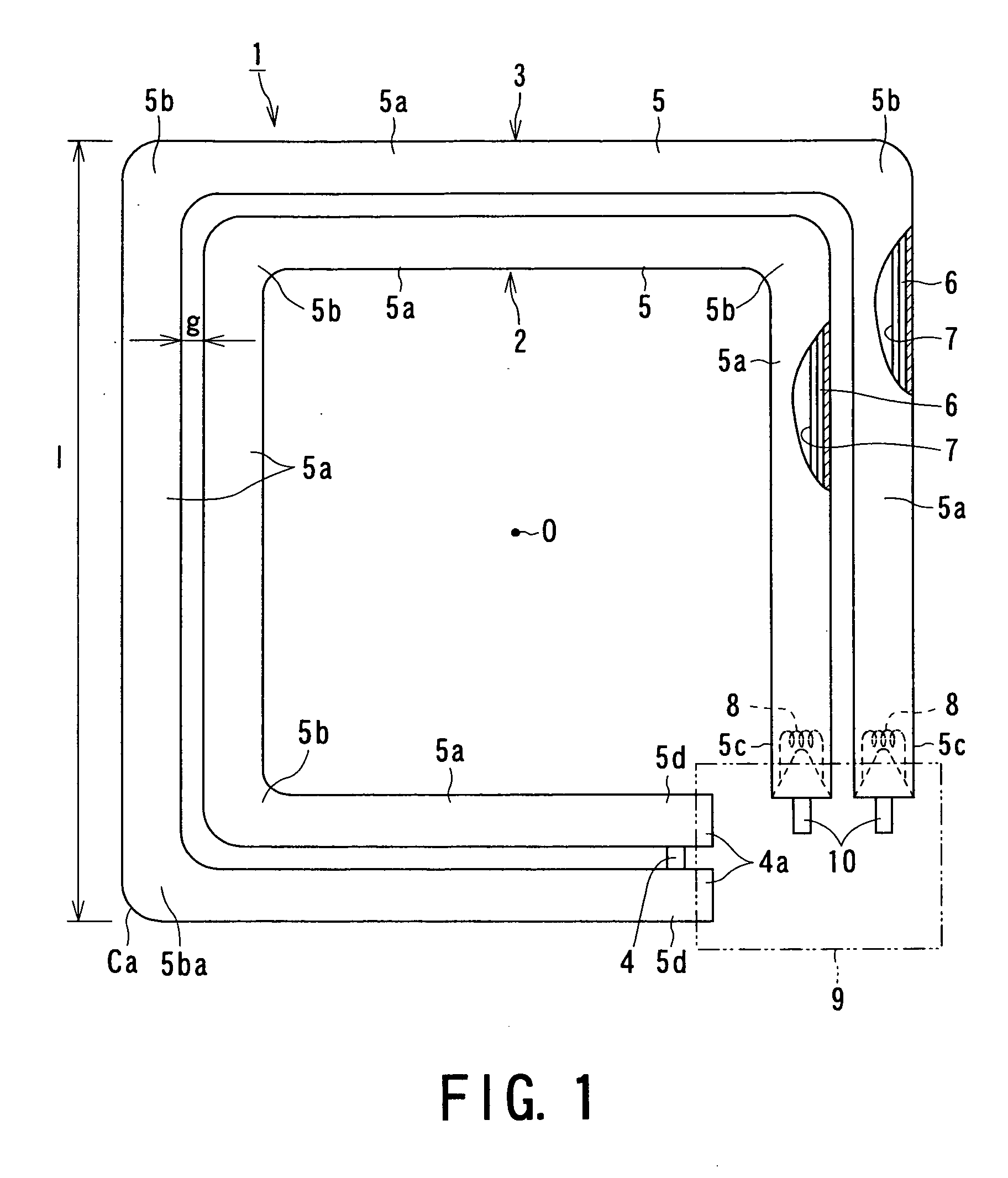
[0087]FIG. 1 is a front view of the fluorescent lamp 1 according to the present invention. The fluorescent lamp 1 is structured by disposing, outside an inner bulb 2 having a rectangular shape in its front view, an outer bulb 3 having a rectangular shape, which is slightly larger than the inner bulb 2 and substantially similar thereto so as to be placed concentrically with the inner bulb 2 at a predetermined gap “g” and connecting these bulbs to each other through a connection portion 4 to thereby form a single unit of double tube (a double-tube bulb).

[0088] These inner and outer bulbs 2 and 3 are formed of glass bulbs 5, 5, respectively, each of which is composed of four straight tube portions, each having a circular cross section, substantially into a square shape so that an intersecting point of diagonal lines of this square shape is placed at a point “O”. The glass bulbs 5, 5 are formed of soft glass such as soda lime glass or lead glass and they may be formed of hard glass such...

second embodiment

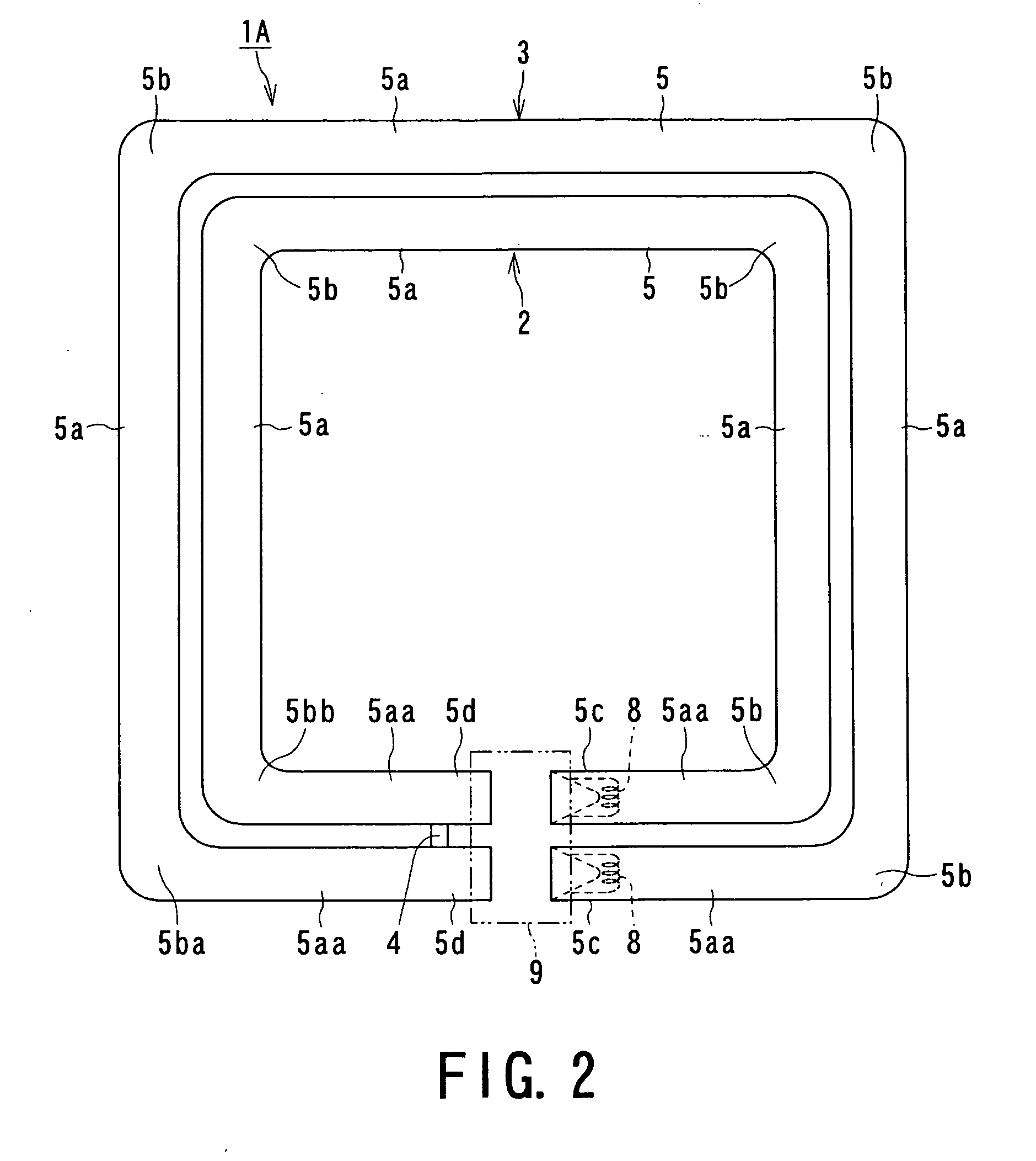
[0112]FIG. 2 is a front view of the fluorescent lamp 1A according to the present invention. The fluorescent lamp 1A is characterized in that each of the inner and outer bulbs 2 and 3 is formed by connecting five straight tube bulbs to each other so as to form four bent portions 5b, in the above-described fluorescent lamp 1.

[0113] More specifically, in the inner and outer bulbs 2 and 3, one side of the square shape of the respective glass bulb 5 is composed of straight tube portions 5a a, 5a a each having a half length of the other side thereof, a pair of electrodes 8, 8 are provided on the end portions of the straight tube portions 5aa, 5aa, respectively, to form the electrode-sealed end portions 5c, 5c, and on the other hand, the other end portions thereof are provided as the connection portion-side end portions 5d, 5d, respectively. The base 9 is mounted so as to straddle a region among both the electrode-sealed end portions 5c, 5c and both the connection portion-side end portions...

fourth embodiment

[0118]FIG. 4 is a front view of the fluorescent lamp 1C according to the present invention. The fluorescent lamp 1C is characterized in that the gap “Ld” between the outer end surface 5co of the electrode-sealed end portion 5c in the axial direction thereof and the outer end surface 5do of the connection portion-side end portion 5d in the axial direction thereof is decreased, in the above-described fluorescent lamp 1B. The remaining structural features are identical to those of the fluorescent lamp 1B as shown in FIG. 3.

[0119] More specifically, in the conventional double-circular fluorescent lamp 321 as shown in FIG. 21, the electrode-sealed end portions 327 and 328 and the end portions on the side of the connection portion 324 are curved as mentioned above, with the result that gaps “La” and “Lb” on the inner peripheral side and the outer peripheral side between the end surfaces 327a and 328a of the electrode-sealed end portions 327 and 328 and the opposing outer end surfaces 329a...


PUM


Abstract

There is provided a multi-ringed bulb including a plurality of ring bulbs in which a plurality of straight tube portions having an outside diameter of from 12 to 20 mm are connected to each other through bent portions on a same plane. Electrodes are provided hermetically at respective ends of outermost and innermost bulbs of the plurality of ring bulbs. A connection portion connects other adjacent ends of the outermost and innermost bulbs to each other so that the outermost and innermost bulbs communicate with each other, to form a single discharge path. A phosphor layer is formed on inner surfaces of at least the straight tube portions 5a of the inner and outer bulbs. The multi-ringed structure bulb is filled with discharge medium. The above-mentioned structure permits to provide a fluorescent lamp and a lighting apparatus, which have a small strain in the inner and outer bulbs, a high strength and an excellent luminous efficiency.

Description

TECHNICAL FIELD [0001] The present invention relates to a fluorescent lamp and a lighting apparatus utilizing such a fluorescent lamp. BACKGROUND OF THE INVENTION [0002] As a conventional double-ringed fluorescent lamp, there is known, for example, as shown in FIG. 21, a double-circular fluorescent lamp 321. In such a double-circular fluorescent lamp 321, there is provided, on the outer side of an inner ring glass bulb 322 having ring shape, an outer ring glass bulb having a ring shape and a larger diameter than the inner ring glass bulb so as to be placed concentrically on the same plane. A connection portion 324 connects respective discharge paths of the inner and outer ring glass bulbs 322, 323 to each other to form a single discharge path so that an increased length of the discharge path can enhance the total luminous flux and the luminous efficiency (as disclosed, for example, following Patent Document 1). [0003] Such a kind of fluorescent lamp has an increased length of the di...

Claims


Application Information

Patent Timeline
Patent Type & Authority Applications(United States)
IPC IPC(8): H01J1/62H01J63/04H01J61/12H01J61/30H01J61/32H01J61/72
CPCH01J61/322H01J61/327H01J5/50H01J61/72
Inventor YAMADA, ICHIROTODA, NAOYUKINISHIMURA, KIYOSHISHIBAHARA, YUSUKEOOTANI, KIYOSHIYOSHIDA, MASAHIKO
Owner TOSHIBA LIGHTING & TECH CORP
Why Eureka
Try Eureka