Stepped outlet turbine airfoil

a turbine and airflow technology, applied in the direction of machines/engines, liquid fuel engines, mechanical equipment, etc., can solve the problems of reducing the overall efficiency of the engine, reducing and correspondingly limited internal cooling space, so as to improve the durability of the airflow and improve the cooling effect of the discharged air. , the effect of improving the cooling efficiency of the discharged air

Inactive Publication Date: 2006-04-06
GENERAL ELECTRIC CO
View PDF20 Cites 15 Cited by
  • Summary
  • Abstract
  • Description
  • Claims
  • Application Information

AI Technical Summary

Benefits of technology

[0015] Accordingly, it is desired to provide a turbine airfoil having impro...

Problems solved by technology

The cooling air is typically compressor discharge air which is diverted from the combustion process and therefore decreases overall efficiency of the engine.
The wider portion of the airfoil has sufficient internal space for accommodating various forms of internal cooling circuits and turbulators for enhancing heat transfer cooling inside the airfoil, whereas the relatively thin trailing edge has correspondingly limited internal cooling space.
The divergence or diffusion angle of the outlet slots is typically limited to abou...

Method used


Image

  • Stepped outlet turbine airfoil
  • Stepped outlet turbine airfoil
  • Stepped outlet turbine airfoil

Examples


Embodiment Construction

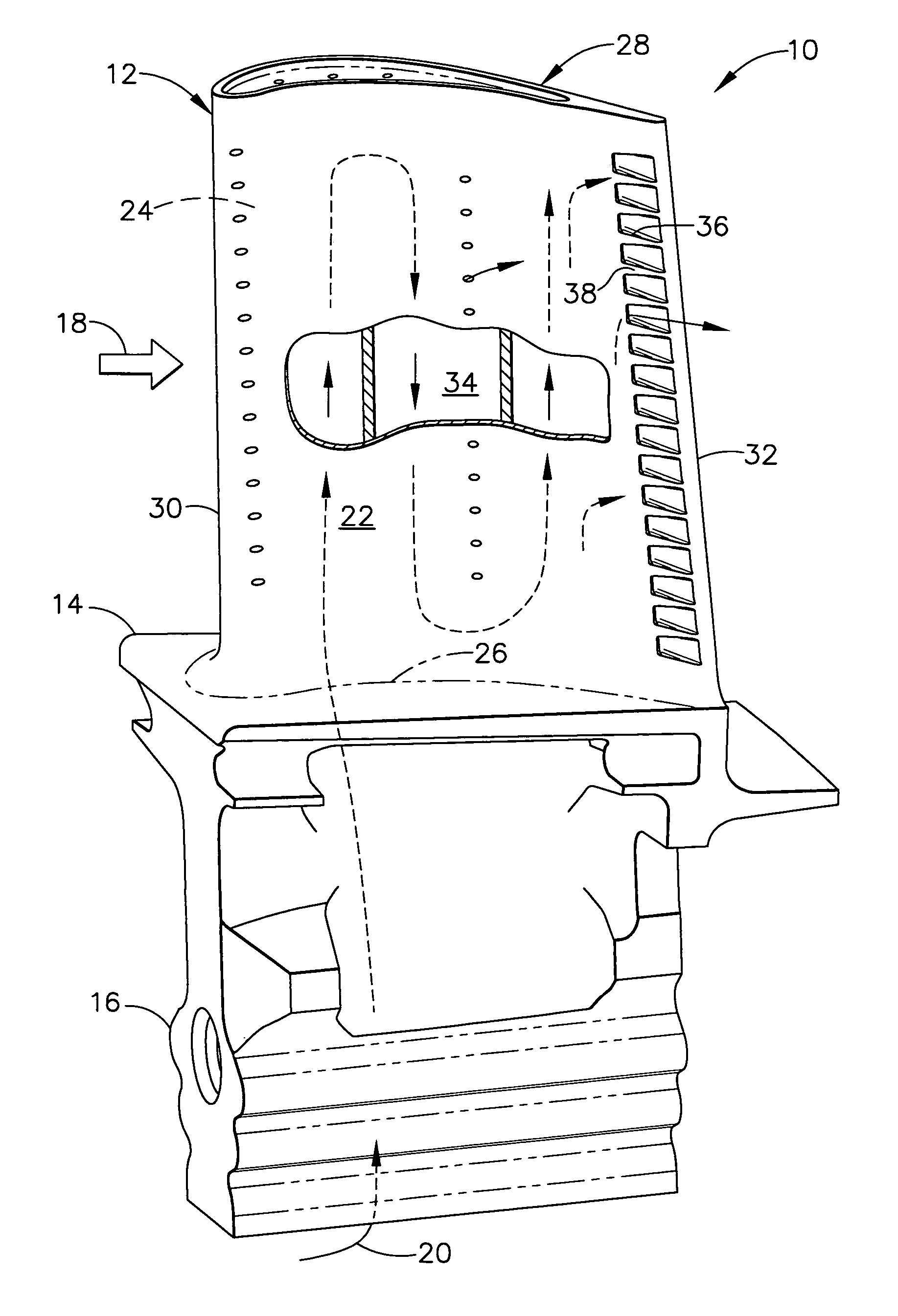
[0024] Illustrated in FIG. 1 is an exemplary first stage turbine rotor blade 10 for use in a gas turbine engine for aircraft, marine, or industrial applications. The blade includes an airfoil 12 integrally formed with a platform 14 and an axial entry dovetail 16 for being mounted in the perimeter of a supporting rotor disk (not shown).

[0025] During operation, combustion gases 18 are generated in the engine and flow downstream over the turbine airfoil 12 which extracts energy therefrom for rotating the disk supporting the blade for powering the compressor (not shown). Air 20 pressurized in the compressor is mixed with fuel and ignited for generating the hot combustion gases, and a portion of that pressurized air is suitably channeled to the blade for cooling thereof during operation.

[0026] More specifically, the airfoil 12 includes a generally concave pressure sidewall 22 and a circumferentially or laterally opposite, generally convex suction sidewall 24. The two sidewalls extend l...


PUM


Abstract

A turbine airfoil includes an internal cooling circuit between opposite pressure and suction sidewalls. The pressure sidewall includes a row of outlet slots for the circuit separated by converging partitions. Each slot includes an inlet, throat, and diverging outlet. Each of the partitions includes a step in a converging sidewall thereof for increasing divergence of the slots to diffuse coolant discharged therethrough.

Description

BACKGROUND OF THE INVENTION [0001] The present invention relates generally to gas turbine engines, and, more specifically, to turbine airfoil cooling. [0002] In a gas turbine engine air is pressurized in a compressor and mixed with fuel in a combustor for generating hot combustion gases. The hot gases are channeled through various stages of a turbine which extract energy therefrom for powering the compressor and producing work, such as powering an upstream fan in a typical aircraft turbofan engine application. [0003] The turbine stages include stationary turbine nozzles having a row of hollow vanes which channel the combustion gases into a corresponding row of rotor blades extending radially outwardly from a supporting rotor disk. The vanes and blades have corresponding airfoil configurations, and are hollow with corresponding cooling circuits therein. Since the heat loads from the combustion gases vary over the pressure and suction sides of the vanes and blades, the cooling circuit...

Claims


Application Information

Patent Timeline
IPC IPC(8): F01D5/18
CPCF01D5/186F01D5/187Y02T50/671Y02T50/673Y02T50/676F05D2260/202Y02T50/60
Inventor MANNING, ROBERT FRANCISDEMARCHE, THOMAS EDWARDFLODMAN, DAVID ALLEN
Owner GENERAL ELECTRIC CO
Why Eureka
Try Eureka